


Installation 3000TA- EU
Teledyne Analytical Instruments 20
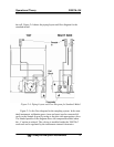
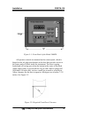
The small circular orifice should face away from the back of the unit
(against the direction of gas flow).
For positive pressures less than 5 psig use the low-pressure
restrictor without the blue dot in the Sample-in line.
For vacuum service (5-10 in Hg), use the restrictor without the
blue dot sticker and union but attach it to the Exhaust Out port. The
small circular orifice should face toward the back of the unit (against the
direction of gas flow).
Remove the blue sticker from the restrictor before using.
Warning: Operating the unit without restrictors can cause
damage to the micro-fuel cell.
The unit is manufactured with 1/4 inch tube fittings, and 6 mm
adapters are supplied for metric system installations. For a safe
connection:
1. Insert the tube into the tube fitting, and finger-tighten the nut
until the tubing cannot be rotated freely, by hand, in the
fitting. (This may require an additional 1/8 turn beyond
finger-tight.)
2. Hold the fitting body steady with a backup wrench, and with
another wrench rotate the nut another 1-1/4 turns.
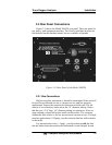
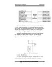
SAMPLE IN:
In the standard model, gas connections are made at the
SAMPLE IN
and
EXHAUST OUT connections. Calibration gases must be tee'd into
the Sample inlet with appropriate valves.
The gas pressure in should be reasonably regulated. Pressures
between 2 and 50 psig are acceptable as long as the pressure, once
established, will keep the front panel flowmeter reading in an acceptable
range (0.1 to 2.4 SLPM). For non-pressurized sample or very low
pressure, (2 psig or less) vacuum service plumbing is recommended.
Exact figures will depend on your process.
If greater flow is required for improved response time, install a
bypass in the sampling system upstream of the analyzer input.