


Performance Verificati o n
32
P5205 Instruction Manual
15. Set the calibration generator for 10 V output. Set the attenuation
button on the probe to 50X (in).
16. Record the DC amplitude of the square wave (∼10V) and divide
1/100
th
of this into only the amplitude of the oscilloscope (refer
to step 6). Verify that only the probe gain accuracy is ᐔ3%.
17. Reduce the amplitude on the generator to minimum then disable
the generat or output, leaving the setup connected for the next
procedure.
Bandwidth
1. Connect the Modified BNC adapter through a 50 Ω terminator to
the leveled sine wave output of the generator (AUX, Sine,
50 Ω load).
WARNING. To reduce the risk of electric shock, ensure the generator
output is disabled before modifying/disconnecting test setup or
connect ions since exposed metal may at a hazardous potential. It is
recommended that the generator output amplitude be reduced to
minimum prior to disabling the output.
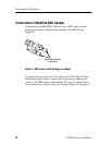
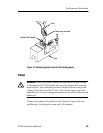
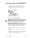
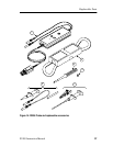
2. Attach the differential probe input lead s (wit hout attachment
accessories) by sliding the banana plug of the leads onto the
binding posts metal sleeves on the Modified BNC adapter (see
Figure 13 on page 31).
3. Set the bandwidth on the probe to FULL and the attenuation
button to 50X.
4. Set the Volts/Division on channel 1 of the oscilloscope to
500 mV, and sec/div to 20 s. Set the trace to the center of the
oscilloscope.
5. Reduce the amplitude on the generator to m inimum then enable
the output.
6. Set the sine wave generator to 50 kHz, and adjust the amplit ude
to 3.00 V as measured on the oscilloscope.