Operating Basics
14
P5205 Instruction Manual
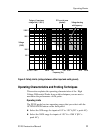
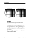
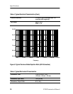
With extension leads
Without extension leads
50 ns/div 50 ns/div
250 mv/div
250 mv/div
Figure 4: HF Transient response with and without extension leads
Probe Loading
When you touch your probe tip to a circuit element, you are
introduci ng a new resistance, capacitance, and induct ance into the
circuit.
Frequency and impedance of the source determine how much the
probe loads the circuit you are measuring. As the frequency of the
source starts to increase beyond 1 kHz, the input impedance of the
probe begins to decrease. The lower the impedance of the probe
relative to that of the source, the more the probe loads the circuit
under test. For a graph of frequency versus input impedance, refer to
Figure 6 on page 19.
The probe has virtually no loading effect on sources with relatively
low impedance and low frequency.


