


37
930486 Rev.A
36
930486 Rev.A
IX. SET-UP, ADJUSTMENT & USE
Q. CHECK-OUT
Once the wheelchair is assembled and adjusted, it should roll smoothly
and easily.All accessories should also perform smoothly.
After the wheelchair has been set up be sure the chair performs to your speci-
fied operational settings (see pages 38-42). If the chair does not perform to spec-
ifications, turn the wheelchair OFF immediately and reprogram operational speci-
fications using the QTRONIX Programming Pad.
Repeat this procedure until the wheelchair performs to specifications
before attempting active use of the wheelchair.
If you have any problems, follow these procedures:
1. Review the set-up and check-out section and operating guide to
make sure chair was properly prepared.
2. If your problem persists, contact your authorized supplier. If you still
have a problem after contacting your authorized supplier, contact
Sunrise customer service. See the introduction page for details on
how to contact your authorized supplier or Sunrise customer service.
IX. SET-UP, ADJUSTMENT & USE
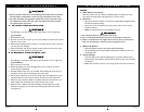
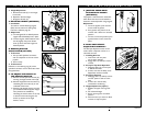
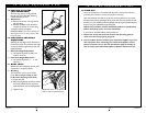
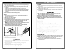
N. PARAPAK SEAT SLING
(SEAT FRAME ONLY)
The seat sling tension can be adjusted
through use of the VELCRO
®
retaining
material beneath the seat.
1. Adjustment
a) Remove the screws retaining the left
side seat sling.
b) Readjust VELCRO
®
style material to
increase the tension in the seat sling.
c) Replace screws and tighten.
Important Note: If there is any difficulty in re-
attaching the screws, try using a probe to help
line up the holes.
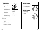
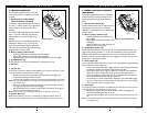
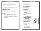
O. SEAT HEIGHT AND ANGLE
ADJUSTMENT
Adjusting the seat height can be done both at
the front and at the rear of the seat. Seat angle
can also be varied through front and rear seat
height adjustment.
1. Rear Seat Height Adjustment
a) Use positioning holes (A & B) and
receiver notch (C).
2. Front Seat Height Adjustment
a) Use positioning holes (I, II, i, ii) and
hole set (1).
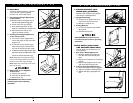
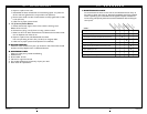
P. WHEEL LOCKS
Wheel locks are installed by Sunrise when
requested on the Quickie S-525
1. Mounting
The wheel lock mounts to the S-525
frame. Use a torque setting of 100
in./lbs when adjusting wheel locks.
a) Loosen bolt (D).
b) Slide mounting bracket toward rear wheel
until clamp embeds into tire to prevent
wheel movement when in locked position.
c) Tighten screw.
Note: Brake shown in rear position.
Hole F is used on standard position
D
C
I
II
1
i
ii
B
A
F