Installation
MI 17
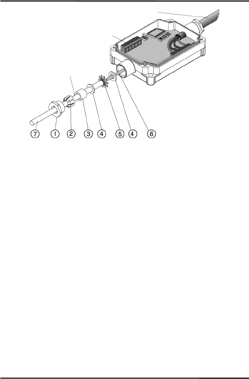
Figure6:ConnectingofCablestotheElectronicBox
5. Putthefollowingonthecable(asshowninthefigure
above):
the cap (1), the plastic compression fitting (2), the rubber
washer(3)andoneofthemetalwashers(4).
6. Spreadthecable shield(5) andthenslip thesecond metal
washer(4)onthecable.Notethattheshieldmustmakegood
contacttobothmetalwashers.
7. Slip
the wires (6) into the electronic box far enough to
connecttothepowerandoutputterminals.
8. Screwthecap(1)intotheelectronicsbox.Tightensnuggly.
Donotovertighten.
9. Connectthewires(6)tothepowerandoutputterminalson
theprintedcircuitboard.
Cable that has to be
installed b
y
the user
Output signal and
p
ower connector bloc
k
Preinstalled cable
to sensor head


