


Stylus www.pridemobility.com 25
V. CARE AND MAINTENANCE
WARNING! Never use any chemicals to clean a vinyl seat, as they may cause the seat to become
slippery or dry out and crack. Use soapy water and dry the seat thoroughly.
Wheel Replacement
If you have pneumatic tires and you have a flat tire, you can replace the tube. If your wheelchair is equipped with
a solid tire insert, then you must replace the entire wheel assembly. Replacement tires, tubes, and wheel assem-
blies are readily available through your authorized Pride Provider.
WARNING! The wheels on your wheelchair should only be serviced or replaced by an authorized
Pride Provider or a qualified technician.
WARNING! When changing a tire, remove the drive wheel. If any further disassembly is required,
deflate the tire completely or it may explode.
To replace a pneumatic tire tube:
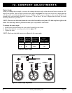
1. Remove the drive wheel from the frame. See figure 11 or 12.
2. Make sure that the tube is deflated completely.
3. Use several tire levers to pry the tire from the rim. Tire levers are available from a bicycle shop.
4. Remove the old tube.
5. Inflate the new tube with enough air so that it just starts to take shape.
6. Insert the tube into the tire.
7. Use the tire levers to secure the tire back onto the rim.
8. Inflate the tire to the pressure recommended on the sidewall. Always use a regulated air source.
9. Reinstall the drive wheel to the frame. Make sure that the wheel axle is snapped securely into the frame
bracket.
Manual Wheel Locks
After several months of use, you may find it necessary to adjust the wheel locks so that they lock securely when
engaged. You also may need to adjust them after changing the drive wheel position.
WARNING! If your wheelchair is equipped with pneumatic tires, make sure they are inflated to
the pressure recommended on the sidewall of the tire.
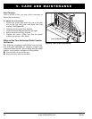
To adjust each manual wheel lock:
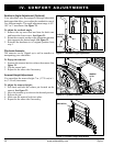
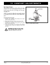
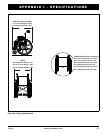
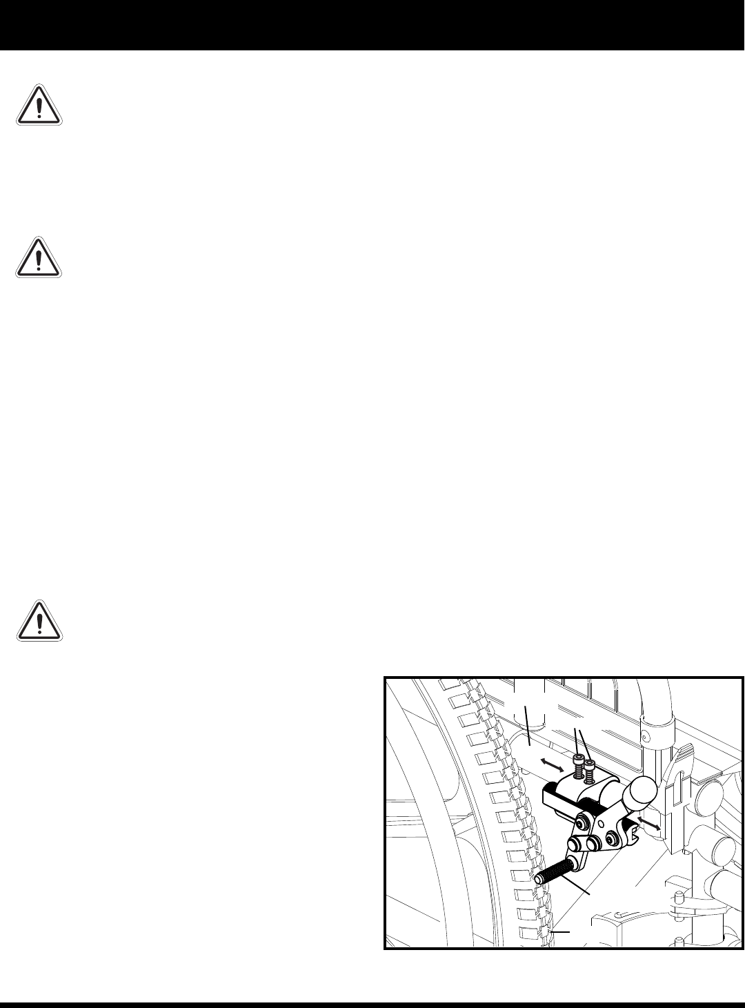
Figure 27. Manual Wheel Lock Adjustment
1. Disengage the wheel lock. See figure 6 or 7. The
wheel lock should be 1/4 in. (0.64 cm) away from the
tire for both pneumatic and solid tires.
2. Loosen the hardware that fastens the wheel lock to
the frame. See figure 27.
3. Reposition the wheel lock so that it is 1/4 in. (0.64
cm) away from the tire and perpendicular to the plane
of the tire.
4. Tighten the hardware that fastens the wheel lock to
the frame.
5. Engage the wheel lock and note the position of the
blade.
6. Reposition the wheel lock if necessary.
7. Repeat the procedure for the other side.
WHEEL LOCK
BLADE
HARDWARE
TIRE
FRAME