


22 www.pridemobility.com Stylus
IV. COMFORT ADJUSTMENTS
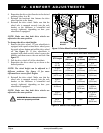
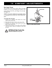
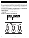
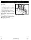
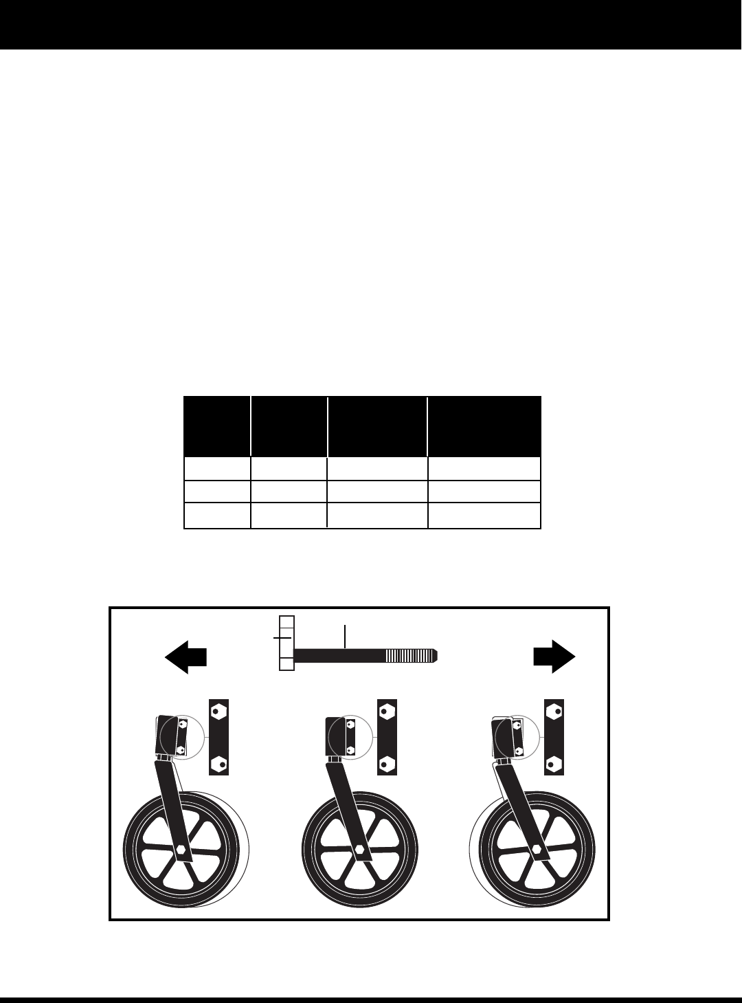
Figure 26. Caster Angle Adjustment
TOP BOLT
BOLT SHAFT
POSITION 1. POSITION 2. POSITION 3.
AFT
FORE
BOLT HEAD
Caster Top Bolt Bottom Bolt Caster
Position Position Position Wheel Angle
1 Fore Aft 95°
2 Fore Fore 90°
3 Aft Fore 85°
Figure 25. Caster Angles
BOTTOM
BOLT
Caster Angle
When you change the seat angle, you must also change the caster angle so that the caster barrels remain at a 90°
angle to the ground. There are three possible caster angles. See figure 26. If the front of the seat is higher than the
rear, the caster assembly should be in postion 1. If there is little or no seat dump (i.e., the seat is parallel to the
ground), the caster assembly should be in position 2. If the rear of the seat is higher than the front, the caster
assembly should be in position 3.
NOTE: There are two bolts that fasten the caster wheel assembly to the frame. The bolt shafts are offset to the
heads. The bolt shafts must be positioned either fore or aft relative to the holes.
To change the caster angle:
1. Remove the bolts that fasten the caster wheel assembly to the frame.
2. Reposition the bolts according to the table in figure 25.
3. Tighten the bolts.
NOTE: Make sure that both casters are adjusted to the same angle.