


16 www.pridemobility.com Stylus
IV. COMFORT ADJUSTMENTS
COMFORT ADJUSTMENTS
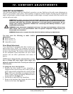
After becoming familiar with your wheelchair’s operation, you may find the need to make some adjustments to
increase your comfort, such as drive wheel position, swing-away footrest length, elevating leg rest length and
angle, calf pad height, seatback height, armrest height, seatback angle, seat angle, manual wheel lock tension, seat
tension, and caster angle.
WARNING! The center of gravity of your wheelchair was factory set to a position that meets the
needs of the demographic majority of users. Your authorized Pride Provider has evaluated your
wheelchair and made any necessary adjustments to suit your specific requirements. Do not
change your seating configuration without first contacting Pride Mobility Products or your
authorized Pride Provider.
WARNING! Some wheelchair components are heavy. You may need assistance to lift or carry
them. Please refer to the specifications table for specific component weights before you
disassemble the wheelchair.
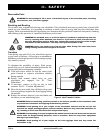
WARNING! Remove the occupant from the wheelchair before making any adjustments.
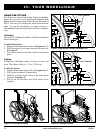
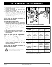
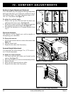
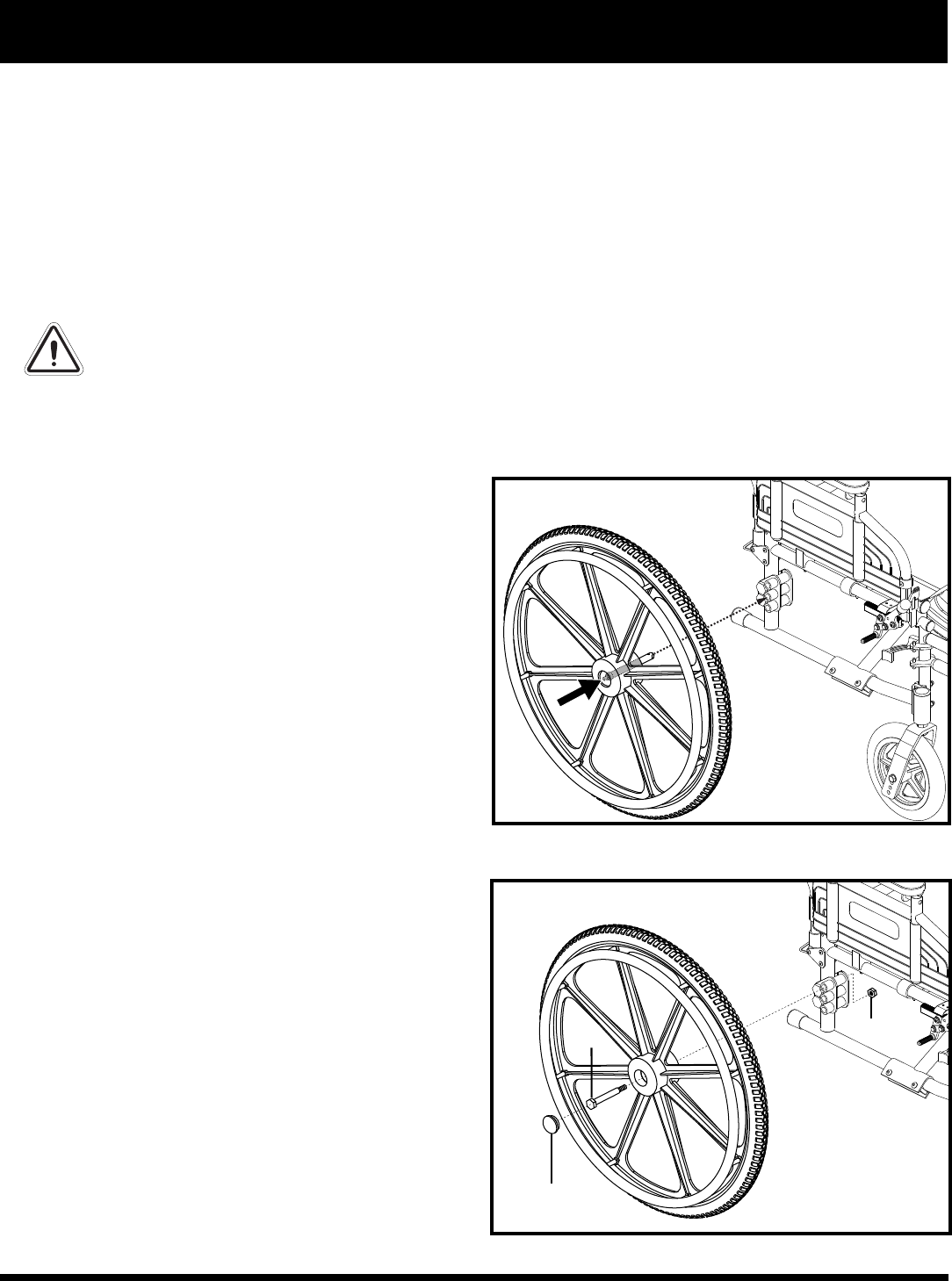
Figure 11. Quick Release Drive Wheel
You may need the following to make comfort
adjustments:
Metric socket set
Metric hex key set
Adjustable wrench
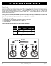
Drive Wheel Adjustment
Your wheelchair is equipped with either a bolt-on or a
quick-release drive wheel. The location of the drive
wheel center bolt and nut on the axle bracket determines
the drive wheel height. The location of the axle bracket
on the wheelchair frame determines the drive wheel
position and can affect performance and center of
gravity.
NOTE: If you change the drive wheel position, you may
have to change the caster height, caster angle, and
adjust the manual wheel lock. Consult your authorized
Pride Provider.
To change the drive wheel position:
1. Remove the drive wheel. If your wheelchair is
equipped with a quick-release drive wheel, press the
quick-release button and pull the drive wheel off. See
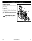
figure 11. If your wheelchair is equipped with a bolt-
on drive wheel, remove the hubcap, and then remove
the nut and bolt. See figure 12.
2. Pull the drive wheel off of the wheelchair.
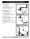
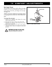
3. Remove the hardware that fastens the drive wheel
bracket to the frame. See figure 13.
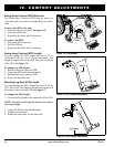
NUT
BOLT
HUBCAP
Figure 12. Bolt-on Drive Wheel