Jazzy 1122 www.pridemobility.com 31
VII. OPERATION
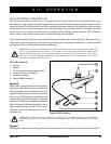
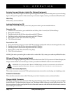
Actuator Keys and Actuator Lights (For Optional Equipment)
Actuator keys and actuator lights are used for optional equipment such as power elevating seats or power elevating
leg rests. For specific operation of the actuator keys and actuator lights, contact your authorized Pride Provider.
Horn Key
The horn key activates the horn.
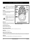
Locking/Unlocking the VSI
The VSI has a feature that enables you to lock your power chair to prevent unauthorized use.
To lock the VSI:
1. With the VSI switched on, press and hold the on/off key. After 1 second, the VSI should beep.
2. Release the on/off key.
3. Push the joystick to the full forward position until the VSI beeps.
4. Pull the joystick to the full rearward position until the VSI beeps.
5. Release the joystick. There should be a long beep.
6. The VSI is now locked.
To unlock the VSI:
1. Press the on/off key and power on the VSI. The maximum speed/profile indicator should ripple side to side.
2. Push the joystick to the full forward position until the VSI beeps.
3. Pull the joystick to the full rearward position until the VSI beeps.
4. Release the joystick. There should be a long beep.
5. The VSI is now unlocked.
NOTE: If the above procedure fails to either lock or unlock the VSI, contact your authorized Pride Provider.
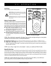
Off-board Charger/Programming Socket
The off-board charger/programming socket is located on the front of the VSI. If you use an off-board charger, the
charger current should not exceed 8 amps. Contact your authorized Pride Provider for more information.
WARNING! Only chargers with Neutrik NC3MX plugs should be connected to the off-board
charger/programming socket. See your authorized Pride Provider for more information.
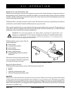
Actuator Connector (Optional)
The actuator connector connects the VSI to optional powered systems such as an elevating seat or lighting system.
Controller Connector
The controller connector connects the VSI to the power chair’s batteries, motors, and motor brakes.
Charger Inhibit Connector
The charger inhibit connector connects the VSI to the onboard battery charger. This connection provides an inhibit
that disables the VSI when the battery charger is on. The charger inhibit connector is coded with colored dots. The
dots are positioned so that you align the flat side of the male connector with the flat side of the female connector
before making the connection.


