


Jazzy 1122 www.pridemobility.com 15
III. YOUR POWER CHAIR
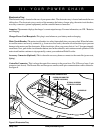
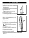
Electronics Tray
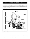
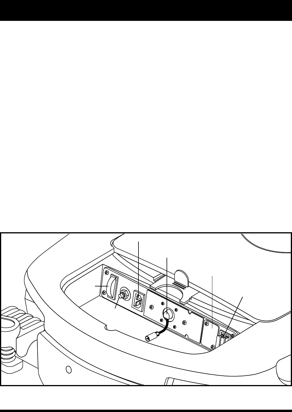
The electronics tray is located on the rear of your power chair. The electronics tray is located underneath the rear
sliding door. The electronics tray consists of the ammeter, the battery charger plug, the main circuit breaker,
accessory connector (optional equipment), and the controller harness connectors.
Ammeter: The ammeter displays the charger’s current output in amps. For more information, see VIII. “Batteries
and Charging.”
Charger Power Cord Receptacle: This plug is used whenever your battery needs recharging.
Main Circuit Breaker: The main circuit breaker is a safety feature built into your power chair. When the batter-
ies and the motors are heavily strained (e.g., from excessive loads), the main circuit breaker trips to prevent
damage to the motors and the electronics. If the circuit trips, allow your power chair to “rest” for approximately
one minute. Next, push in the circuit breaker button, turn on the controller, and continue normal operation. If the
main circuit breaker continues to trip repeatedly, contact your authorized Pride Provider.
Accessory Connector (Optional): This is where the accessory harness connects to the controller (power seat,
lighting).
Controller Connector: This is where the controller connects to the power base. The VSI uses a large, 9-pin
connector (not shown). The Remote Plus and Europa use smaller, multi-pin communications cable connectors.
See figure 6.
Figure 6. Electronics Tray
AMMETER
OPTIONAL ACCESSORY
CONNECTOR LOCATION
CONTROLLER CONNECTOR
(REMOTE PLUS SHOWN)
CHARGER POWER CORD RECEPTACLE
MAIN CIRCUIT
BREAKER
CHARGER FUSE