


12 Pelco Manual C1487M-D (7/99)
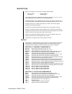
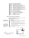
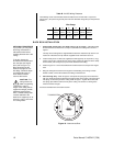
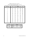
Table B. 24 VAC Wiring Distances
The following are the recommended maximum distances for 24 VAC with a 10-percent
voltage drop. (Ten percent is generally the maximum allowable voltage drop for AC-powered
devices.)
Wire Gauge
20 18 16 14 12 10
30 vA 94 ft 150 ft 238 ft 380 ft 603 ft 960 ft
(28 m) (45 m) (72 m) (115 m) (183 m) (292 m)
75 vA 37 ft 60 ft 95 ft 152 ft 241 ft 384 ft
(11 m) (18 m) (29 m) (46 m) (73 m) (117 m)
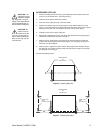
BACK BOX INSTALLATION
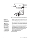
1. Suspended Ceiling Only (for hard ceiling, go to step 2) - Install the ceiling
tile with the back box. Attach a T-rail clip on each side of the ceiling tile as shown in
Figure 7.
The clips for the ceiling tile are supplied with the back box. Attach the clip to the T-rail.
Fasten the L-bracket to the clip with the supplied screw, lock washer and nut.
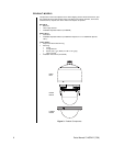
2. Install a safety chain or cable (not supplied) that will support up to 16 pounds (7.3 kg).
Fasten one end to a support structure in the ceiling. Fasten the other end to the safety
chain bracket (refer to Figure 5) to prevent the back box from falling.
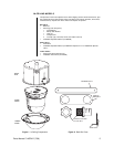
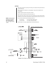
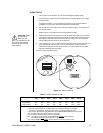
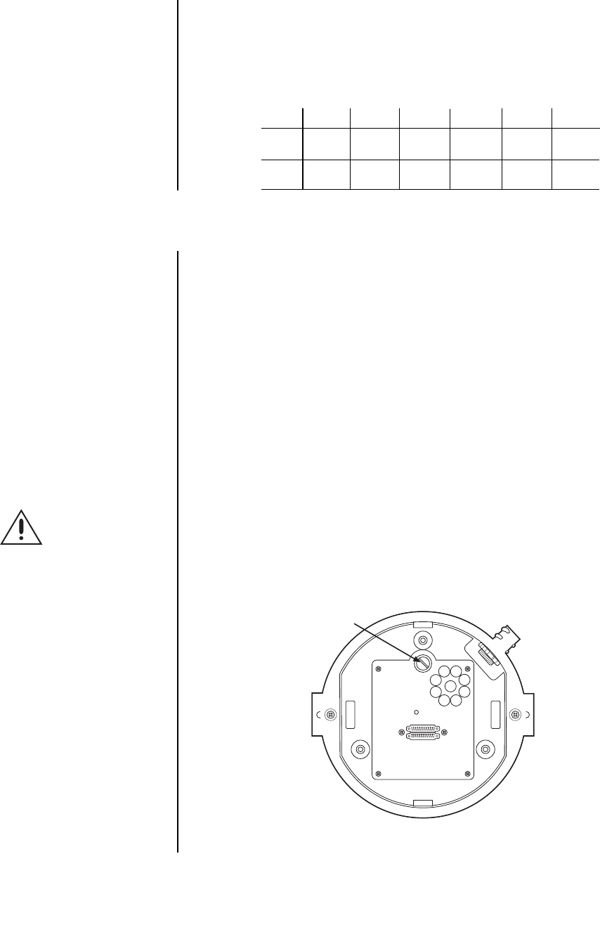
3. Refer to Figure 10. Loosen the thumbscrew inside the back box and open the hinged
door.
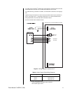
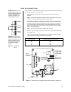
4. Bring the wiring into the back box through the conduit fitting. If the wiring is inside
flexible conduit, connect the conduit to the fitting on the back box.
5. Hard Ceiling Only - Refer to Figure 6. Compress the spring clips on the back box
with your hands and push the back box through the hole in the ceiling. The spring clips
will spring out when they clear the ceiling. Refer to Figure 7. Tighten the screws until
the spring clips hold the back box firmly to the ceiling. You will hear a clicking noise
when the screws are tight.
Proceed to the
Back Box Connections
section.
THUMBSCREW
00096
OPTIONAL PROCEDURE:
If you prefer, you may make
the wiring connections in-
side the back box before
installing the back box in the
ceiling.
To do this, loosen the
thumbscrew inside the back
box and open the hinged
door (refer to Figure 10).
Bring the wiring into the
back box through the con-
duit fitting. Follow the steps
in the
Back Box Connec-
tions
section and then
return to this section.
CAUTION:
The
ceiling must be ca-
pable of supporting
16 pounds (7.3 kg) of
weight. If the ceiling will not
support this weight, provide
additional reinforcement.
Also, a suitable safety chain
must be attached to the
back box to support up to 16
pounds (7.3 kg) in the event
of a ceiling failure.
Figure 10. Interconnect Door