


PAGE 76 — C-30HD — PARTS & OPERATION MANUAL — REV. #4 (03/06/01)
C-30HD — SERVICE PROCEDURES
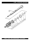
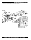
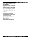
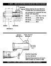
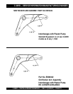
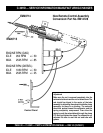
1. CRANKSHAFT AND CAM ASSEMBLY PROCEDURE
A. Set bearing block (part #EM14303) into hydraulic press.
Place bearing cup into bearing block and press in evenly.
Bearing cup should be aligned equally on both sides of bearing
block.
B. Set crankshaft into hydraulic press with the long end
towards the top. Install spacer (part #EM14322), O-ring (part
#EM14326) and bearing cone (part #EM14325) onto
crankshaft. Place bearing block on crankshaft until the bearing
cone is riding in the bearing cup. Insert bearing cone spacer
(part #EM14323) onto crankshaft and inside bearing block.
Install second bearing cone until it is seated inside bearing
cup. Place O-ring and spacer (part #EM14302) on crankshaft.
Set cam weldment on top of spacer. Install crankshaft key and
cam key on cam bushing (part #EM14301). Slide cam bushing
down crankshaft and align the bushing, cam and crankshaft.
Install sleeve over crankshaft and align with hydraulic press.
Install cam bushing bolts loosely. Press bushing down onto
bearing assembly. Leaving pressure on the bushing, tighten
cam bolts evenly to 40-50 foot pounds. Release pressure on
the bushing, re-apply pressure to bushing and tighten bolts
evenly to 40-50 foot pounds. Repeat procedure 3 to 4 times.
After bushing is tight into cam, remove from hydraulic press.
Remove one bolt at a time, using Loctite, install bolts and
torque to 65-70 foot pounds. Counter sink set screw hole and
install dog point set screw and second set screw both with
Loctite.
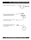
C. Place cam bearing onto crankshaft keeping bearing loose.
*Note: Make sure the eccentric lock is facing toward the outside
of the pumping unit.
D. Set crankshaft assembly into the pump box and align both
bearing assemblies with the pump box mountings.
E. After crankshaft assembly is securely fastened to the pump
box, place sprocket (part #EM14307) onto the cam side of
the crankshaft assembly. Install bushing (part #EM14309) into
sprocket. Align sprocket with sprocket on countershafts and
tighten bolts.
F. Install chain part #EM14308. To adjust, loosen locknuts on
pusher bolts and tighten chain to approximately 1/2” slack in
the chain. Once chain is adjusted properly, tighten down
locknuts.
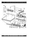
2. BALL AND SEAT REPLACEMENT PROCEDURE
A. Remove 3”x 2” reducer and 3” elbow from the pump outlet.
Remove exhaust gate and Y-manifold (secondary manifold).
Check ball seat and ball stop pin for wear. If any wear is
detected, the part should be replaced. Remove T-manifold
(primary manifold). Check all parts for wear. Remove hopper
and hopper seat and inspect.
B. Loosen the piston nuts and remove the piston cup assembly
and cylinders. Inspect all parts for wear and replace parts with
excessive wear. Check oiler pump for proper operation.
C. Clean all parts thoroughly, removing all foreign material and
concrete slurry. Once parts are clean, install concrete cylinders.
Place oiler plate O-ring in place and coat with oil. Install small
O-ring on piston rod. Run oiler line through the cylinders and
connect in the oiler fitting on the oiler plate. Push oiler plate
into cylinder. Install ring and felt holder, soak felt ring in oil,
then install around felt holder in cylinder. Make sure the bronze
ring is flat, then push it up flush with the ring and felt holder.
Coat piston cup with oil and push it inton the cylinder. Install
bushing into center of piston cup. Put small O-ring on rod, place
face plate on rod and tighten down securely. Repeat these
procedure on the opposite cylinder.
D. Thoroughly check T-manifold, ball stoppings and both steel
balls for wear. Insert an O-ring in the top flange and in the
leading edge of the manifold. Put the manifold onto the primary
side of the pump and install bolts leaving them loose.
E. Check Y-manifold for wear, install all O-rings, ball stop pin,
ball and seat. Align and install Y-manifold to T-manifold and
cylinder assembly. Tighten Y-manifold bolts first before
tightening T-manifold bolts. After manifolds are tight, check O-
rings for slippage.
F. Insert seat into frame hole directly above the T-manifold.
The seat orifice should fit inside the frame itself, then the seat
sits on top of the orifice. On the dura-seat, set the big end of
the seat in the frame. The seat, or the small part of the dura-
seat, fits into the bottom of the hopper.
G. After tightening the manifold bolts and inserting the seats
in place, set the hopper over the seat and align the bolt holes.
Tighten bolts, check O-ring and seat for alignment.
H. Check exhaust gate for wear, install and align gate onto Y-
manifold. Insert O-ring into exhaust gate flange and close gate.
Lock down lever and adjust clamp arm.
I. Install 3” elbow and 3”x 2” reducer. Fill hopper half full and
check for leaks.