5
SETTINGS AND PROCEDURES BEFORE
OPERATION
5.4 Wiring
5.4.1 Precautions for safety devices and wiring
5 - 22
1
OVERVIEW
2
SYSTEM
CONFIGURATION
3
SPECIFICATIONS
4
FUNCTIONS
5
SETTINGS AND
PROCEDURES BEFORE
OPERATION
6
TROUBLESHOOTINGAPPENDIX
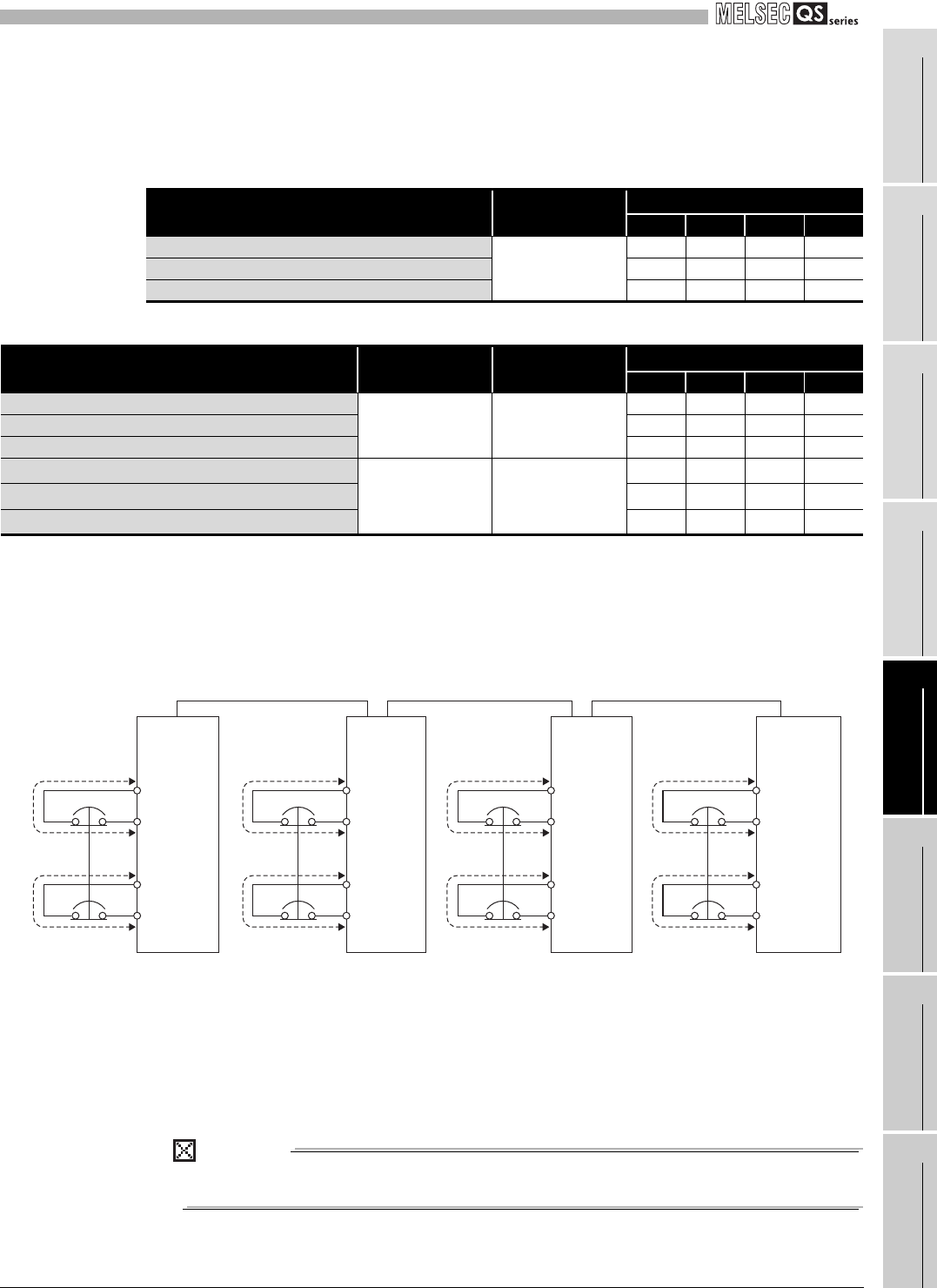
(b) When both main module and extension modules are used in a system
Table 5.6 and Table 5.7 show the maximum wire lengths for input P type and input
N type extension modules, respectively.
* 1: Use the wire whose diameter is between 0.2 and 0.75mm
2
for the QS90SR2SP-Q and
QS90SR2SN-Q.
* 2: Each wire length (a, b, c, and d) corresponds to the same alphabets shown in Figure 5.13.
* 3: When one QS90SR2SN-Q/CC whose first 6 digits of the serial number are "111013" or earlier or
one QS90SR2SN-EX is included
* 4: Use the wire whose diameter is 0.75mm
2
for the QS90SR2SN-Q.
Figure 5.13 System configuration and external wiring diagram
Use a wire with the same length of the wire for X0 for X1.
Table 5.6 Maximum wire length of the safety input when an extension module (input P type) is used
System configuration Diameter
Maximum wire length
*2
a b c d
QS90SR2SP-Q/CC + one QS90SR2SP-EX module
0.2 to 2.5mm
2 *1
50m 50m - -
QS90SR2SP-Q/CC + two QS90SR2SP-EX modules 50m 50m 50m -
QS90SR2SP-Q/CC + three QS90SR2SP-EX modules 50m 50m 50m 50m
Table 5.7 Maximum wire length of the safety input when an extension module (input N type) is used
System configuration
First 6 digits of
serial No.
Diameter
*1
Maximum wire length
*2
a b c d
QS90SR2SN-Q/CC + one QS90SR2SN-EX module
"111014" or later
0.2 to 2.5mm
2 *1
50m 50m - -
QS90SR2SN-Q/CC + two QS90SR2SN-EX modules 50m 50m 50m -
QS90SR2SN-Q/CC + three QS90SR2SN-EX modules 50m 50m 50m 50m
QS90SR2SN-Q/CC + one QS90SR2SN-EX module
*3
"111013" or earlier
0.75 to 2.5mm
2 *4
30m 20m - -
QS90SR2SN-Q/CC + two QS90SR2SN-EX modules
*3
20m 15m 15m -
QS90SR2SN-Q/CC + three QS90SR2SN-EX modules
*3
10m 13.3m 13.3m 13.3m
a: External wire length of the safety input (X0-COM, X1-COM) of the main module
b: External wire length of the safety input (X0-COM, X1-COM) of the first extension module
c: External wire length of the safety input (X0-COM, X1-COM) of the second extension module
d: External wire length of the safety input (X0-COM, X1-COM) of the third extension module
abcd
abcd
First
extension
module
Extension cable Extension cable Extension cable
Second
extension
module
Third
extension
module
Main module
Safety switch Safety switch Safety switch Safety switch
COM
X0
X1
COM
COM
X0
X1
COM
COM
X0
X1
COM
COM
X0
X1
COM


