


5
SETTINGS AND PROCEDURES BEFORE
OPERATION
5.3 Extension Safety Relay Module
5.3.3 Part names and settings
5 - 18
1
OVERVIEW
2
SYSTEM
CONFIGURATION
3
SPECIFICATIONS
4
FUNCTIONS
5
SETTINGS AND
PROCEDURES BEFORE
OPERATION
6
TROUBLESHOOTINGAPPENDIX
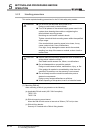
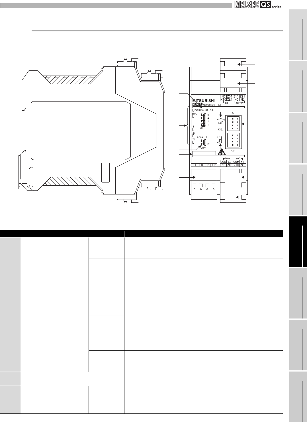
5.3.3 Part names and settings
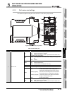
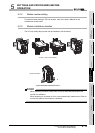
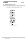
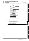
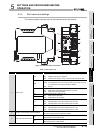
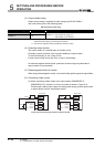
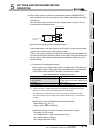
This section explains each part name of the extension safety relay module.
Figure 5.11 Extension safety relay module
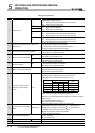
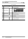
Table 5.3 Part names (1/2)
Number Name Description
1) Indicator LED
PW
Indicates status of the module power supply.
ON: Module power supply is supplied.
OFF: Module power supply is cut off or powered OFF with electric fuse.
ERR.
Indicates an error of the station.
Flash: A self-diagnostics error has occurred, safety power supply is cut off,
or communication with a upper module is disabled.
OFF: Normal
Z
Indicates status of safety output Z.
ON:
OFF:
Safety output is generated (both K0 and K1 are ON).
Safety output is not generated.
X0 Indicates status of safety input (X0, X1).
X1
ON:
OFF:
Safety input is generated.
Safety input is not generated.
K0
Indicates operating status of the internal safety relay K0 (coil status of K0).
ON: Operating status of the internal safety relay K0 is ON.
OFF: Operating status of the internal safety relay K0 is OFF.
K1
Indicates operating status of the internal safety relay K1 (coil status of K1).
ON: Operating status of the internal safety relay K1 is ON.
OFF: Operating status of the internal safety relay K1 is OFF.
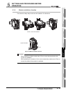
2) Extension communication part terminal block
EA, EB, EG: Data terminal for extension communication
EP: Power supply terminal for extension module
3) Safety input part terminal block
X0
X0: Safety input X0 input terminal
COM: Safety input X0 COM terminal
X1
X1: Safety input X1 input terminal
COM: Safety input X1 COM terminal
1)
7)
10)
5)
6)
2)
4)
1)
8)
9)
3)
5)