5 - 13
5.2 CC-Link Safety Relay Module
5.2.3 Part names and settings
5
SETTINGS AND PROCEDURES BEFORE
OPERATION
Table 5.2 Part names (2/2)
Number Name
Description
1) Indicator LED
Z
Indicates status of safety output Z.
ON:
OFF:
Safety output is generated (both K0 and K1 are ON).
Safety output is not generated.
X0 Indicates status of safety input (X0, X1).
X1
ON:
OFF:
Safety output is generated.
Safety output is not generated.
K0
Indicates operating status of the internal safety relay K0 (coil status of K0).
ON: Operating status of the internal safety relay K0 is ON.
OFF: Operating status of the internal safety relay K0 is OFF.
K1
Indicates operating status of the internal safety relay K1 (coil status of K1).
ON: Operating status of the internal safety relay K1 is ON.
OFF: Operating status of the internal safety relay K1 is OFF.
2)
CC-Link part, extension communication part
terminal block
DA, DB, DG: Data terminal for CC-Link cable
SLD: Shielding wire terminal of CC-Link cable
EA, EB, EG: Data terminal for extension communication
EP: Power supply terminal for extension module
3) Module power supply part terminal block
+ 24V: Module power supply + 24V terminal
24G: Module power supply 24G terminal
4) Safety input part terminal block
X0
X0: Safety input X0 input terminal
COM: Safety input X0 COM terminal
X1
X1: Safety input X1 input terminal
COM: Safety input X1 COM terminal
5)
Safety power supply, start-up
part terminal block
XS
XS0, XS1: Start-up off check terminal
+ 24V: Safety power supply + 24V terminal
24G: Safety power supply 24G terminal
6) Safety output part terminal block
Z00, Z01: Safety relay output terminal
Z10, Z11: Safety relay output terminal
Z20, Z21: Safety relay output terminal
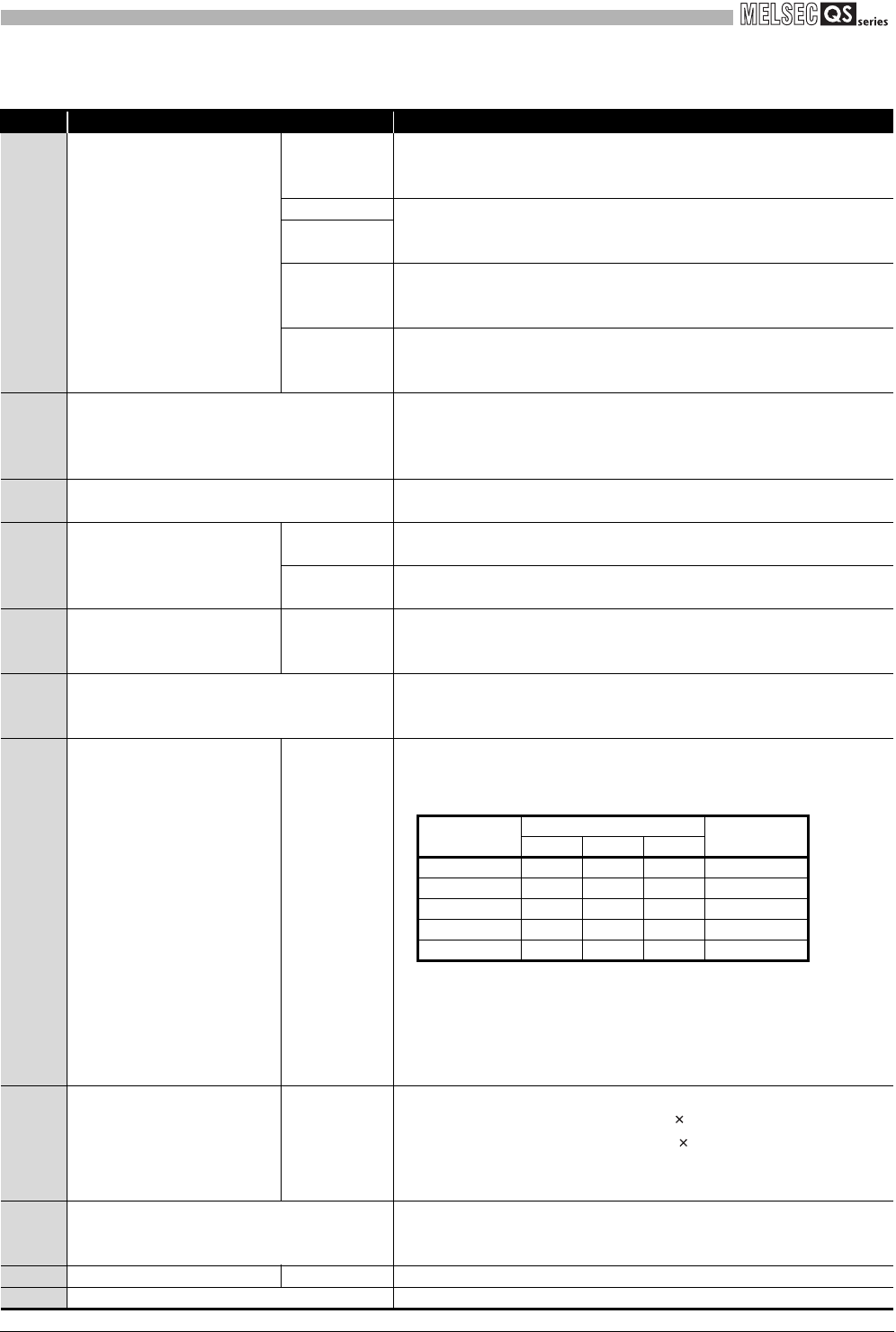
7)
CC-Link transmission speed
terminating resistor setting
switch
1 to 4
A switch for setting transmission speed of the CC-Link system and if
terminating resistor is attached to the CC-Link system or not
•Transmission speed setting (Switch number from 1 to 3)
Set the transmission speed within the range from 0 to 4.
•Setting if CC-Link terminating resistor is attached or not (Switch number 4)
Setting switch LT
ON: Terminating resistor is attached.
OFF: Terminating resistor is not attached.
8)
CC-Link station number setting
switch
STATION No.
A switch for setting the station number of CC-Link system
•Set tens place of the station number with " 10" of "STATION No.".
•Set ones place of the station number with " 1" of "STATION No.".
Set a station number within the range from 1 to 64.
(Repeat use of a station number is not possible.)
9) Start-up mode setting switch
A switch for setting start-up mode
"A" side: Auto mode
"M" side: Manual mode
10) Safety part extension connector OUT A connector for connecting an extension module
11) Serial number display A serial number same as the one shown on the rating plate
Setting
Setting switch status (B RATE)
Transmission
speed
421
0 OFF OFF OFF 156kbps
1OFFOFFON625kbps
2 OFF ON OFF 2.5Mbps
3 OFF ON ON 5Mbps
4 ON OFF OFF 10Mbps


