


3
SPECIFICATIONS
3.5 I/O Signals
3 - 14
1
OVERVIEW
2
SYSTEM
CONFIGURATION
3
SPECIFICATIONS
4
FUNCTIONS
5
SETTINGS AND
PROCEDURES BEFORE
OPERATION
6
TROUBLESHOOTINGAPPENDIX
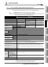
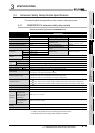
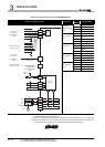
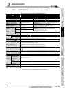
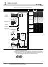
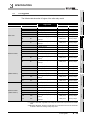
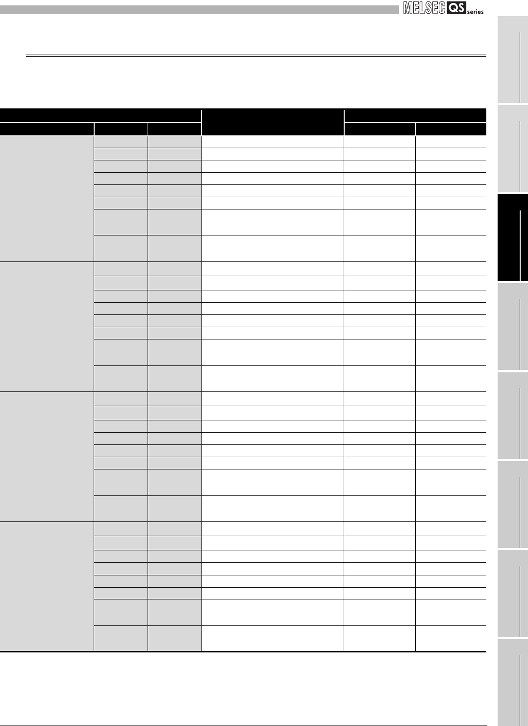
3.5 I/O Signals
The following table shows the I/O signals of the safety relay module.
* 1: The signal is always OFF regardless of the safety input status when the input of the main module
is OFF.
* 2: K0RB and K1RB indicate whether the actual safety relay contacts K0 and K1 are ON, respectively.
This allows a detection of welding of safety relay contact.
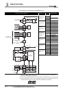
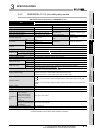
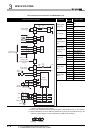
Table 3.8 List of I/O signals
Device number
Signal name
Description
Module Q series CC-Link
ON OFF
Main module
X0 RX0 X0: Safety input 0 Input No input
X1 RX1 X1: Safety input 1 Input No input
X2 RX2 Z: Safety output Output No output
X3 RX3 XS: Start-up input Input No input
X4 RX4 K0: Internal safety relay K0 drive (coil) Relay drive No relay drive
X5 RX5 K1: Internal safety relay K1 drive (coil) Relay drive No relay drive
X6 RX6
K0RB: Internal safety relay K0 output
(contact)
*2
Relay output No relay output
X7 RX7
K1RB: Internal safety relay K1 output
(contact)
*2
Relay output No relay output
Extension module
(station number 1)
X8 RX8
X0: Safety input 0
*1
Input No input
X9 RX9
X1: Safety input 1
*1
Input No input
XA RXA Z: Safety output Output No output
XB RXB XS: Start-up input Input No input
XC RXC K0: Internal safety relay K0 drive (coil) Relay drive No relay drive
XD RXD K1: Internal safety relay K1 drive (coil) Relay drive No relay drive
XE RXE
K0RB: Internal safety relay K0 output
(contact)
*2
Relay output No relay output
XF RXF
K1RB: Internal safety relay K1 output
(contact)
*2
Relay output No relay output
Extension module
(station number 2)
X10 RX10
X0: Safety input 0
*1
Input No input
X11 RX11
X1: Safety input 1
*1
Input No input
X12 RX12 Z: Safety output Output No output
X13 RX13 XS: Start-up input Input No input
X14 RX14 K0: Internal safety relay K0 drive (coil) Relay drive No relay drive
X15 RX15 K1: Internal safety relay K1 drive (coil) Relay drive No relay drive
X16 RX16
K0RB: Internal safety relay K0 output
(contact)
*2
Relay output No relay output
X17 RX17
K1RB: Internal safety relay K1 output
(contact)
*2
Relay output No relay output
Extension module
(station number 3)
X18 RX18
X0: Safety input 0
*1
Input No input
X19 RX19
X1: Safety input 1
*1
Input No input
X1A RX1A Z: Safety output Output No output
X1B RX1B XS: Start-up input Input No input
X1C RX1C K0: Internal safety relay K0 drive (coil) Relay drive No relay drive
X1D RX1D K1: Internal safety relay K1 drive (coil) Relay drive No relay drive
X1E RX1E
K0RB: Internal safety relay K0 output
(contact)
*2
Relay output No relay output
X1F RX1F
K1RB: Internal safety relay K1 output
(contact)
*2
Relay output No relay output