3
SPECIFICATIONS
3.4 Extension Safety Relay Module Specifications
3.4.1 QS90SR2SP-EX extension safety relay module
3 - 10
1
OVERVIEW
2
SYSTEM
CONFIGURATION
3
SPECIFICATIONS
4
FUNCTIONS
5
SETTINGS AND
PROCEDURES BEFORE
OPERATION
6
TROUBLESHOOTINGAPPENDIX
3.4 Extension Safety Relay Module Specifications
This section explains the specifications of the extension safety relay module.
3.4.1 QS90SR2SP-EX extension safety relay module
* 1: Category 4 is complied only when connecting a light curtain of Type 4.
* 2: Manual operation such as start-up switch operation is excluded.
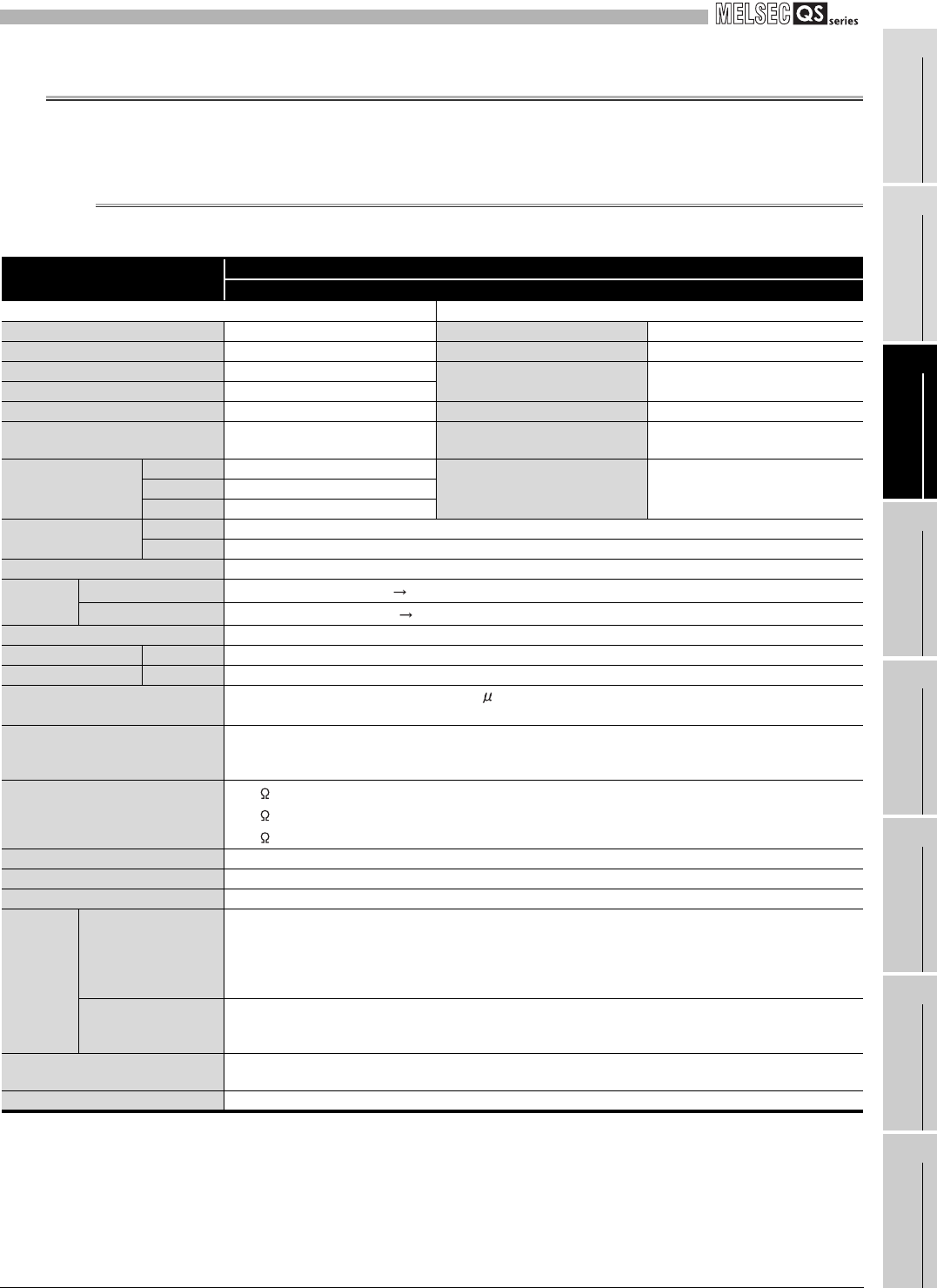
Table 3.6 Performance specifications of QS90SR2SP-EX (1/2)
Item
Extension safety relay module
QS90SR2SP-EX
Input specifications Output specifications
Number of safety input points 1 safety input point (2 inputs) Number of safety output points 1 safety output point (3 outputs)
Number of other input points 1 start-up input point Insulation method Relay insulation
Insulation method Relay insulation
Rated load current
Category 3: 5.0A/point or less
Category 4: 3.6A/point or less
*1
Safety input rated input voltage 24VDC (ripple ratio: within 5%)
Safety input rated input current 4.6mA Minimum switching load 5VDC/5mA
Operating voltage range 20.4 to 26.4VDC
Maximum allowable voltage of
contact
250VAC, 30VDC
Input format
Type P type
Resistance load 250VAC/5A, 30VDC/5AX0 Positive common
X1 Positive common
Relay life
Mechanical Five million times or more
Electrical Hundred thousand times or more
Maximum switching frequency 1,200 times/hour based on the rated control capacity
Response
time
Time until output ON
50ms or less (safety input ON safety output ON)
*2
Time until output OFF
20ms or less (safety input OFF safety output OFF)
Common wiring method All safety inputs and safety outputs are independent.
Module power supply Voltage Supplied from Q series safety relay module or CC-Link safety relay module.
Safety power supply Voltage Supplied from Q series safety relay module or CC-Link safety relay module.
Noise durability
DC type noise voltage: 500Vp-p, noise width: 1 s,
noise frequency: 25 to 60Hz (noise simulator condition)
Dielectric withstand voltage
2,500VAC/1mA or less for 1 minute between safety outputs
2,500VAC/1mA or less for 1 minute between safety input and safety output
2,500VAC/1mA or less for 1 minute between power supply and safety output
Insulation resistance
100M or more, measured with a 500VDC insulation resistance tester between safety outputs
100M or more, measured with a 500VDC insulation resistance tester between safety input and safety output
100M or more, measured with a 500VDC insulation resistance tester between power supply and safety output
Level of protection IP1X
Weight 0.35kg
External connection method Two-piece spring clamp terminal block
Applicable
wire size
Safety input part
Start-up input part
Safety power supply part
Safety output part
terminal block
AWG: 24 to 14, 0.2 to 2.5mm
2
Extension
communication part
terminal block
AWG: 24 to 16, 0.2 to 1.25mm
2
Applicable solderless terminal (bar
terminal)
Refer to Section 5.4.
Applicable DIN rail TH35-7.5Fe, TH35-7.5Al (JIS C 2812 compliant)


