


PATENTS PENDING
32
11921 Slauson Ave. Santa Fe Springs, CA. 90670 (800) 227-4116 FAX (888) 771-7713
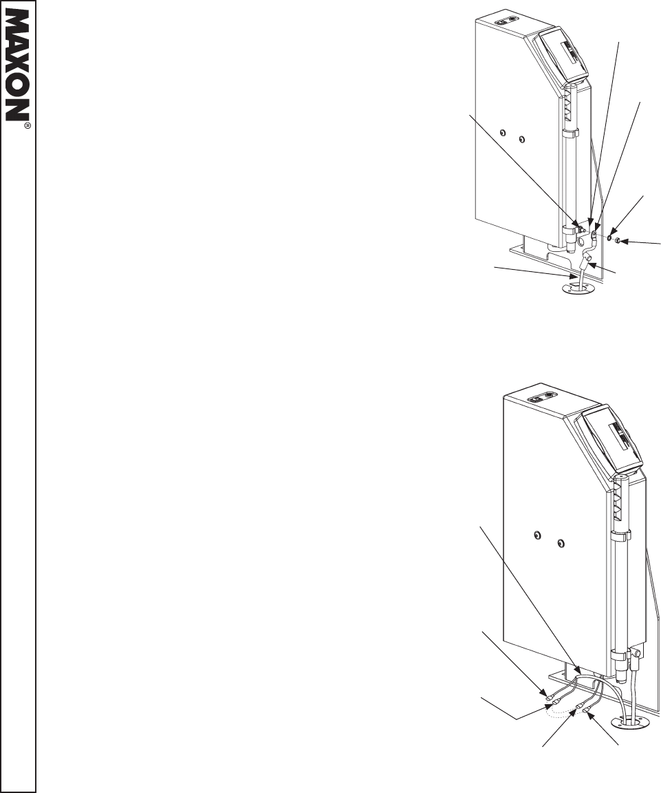
HEX
NUT
2 GA
TERMINAL
LUG
FIG. 32-1
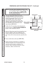
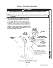
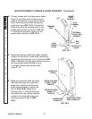
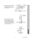
4. Cut any excess wire from long power cable.
Strip 1/2” insulation from the cut end and
install 2 GA terminal lug and shrink tubing.
Next, insert the power cable through the
protective cover (FIG. 32-1). Connect the
cable terminal to the terminal stud on the
power input bracket as shown in FIG. 32-
1. Position the protective cover over the
power cable connection (FIG. 32-1).
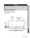
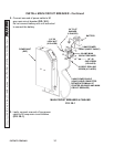
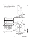
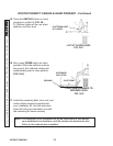
5. Route the interlock cable from safety interlock
system on the vehicle, underneath vehicle fl oor
and through the grommet, and up to the Lift (FIG.
32-2). If possible, use the same cable routing as
the long power cable installed in previ-
ous steps. Secure the interlock cable
every 8”-10”.
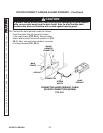
6. Make sure interlock cable will reach
the white-red stripe wire (interlock
signal from vehicle) and the brown
wire (interlock signal to vehicle) on
the Lift (FIG. 32-2). Signal may
be ground or V+. Connect the inter-
lock wires from the vehicle interlock
system to the white-red stripe wire
and brown wire on the Lift (FIG.
32-2).
FIG. 32-2
INTERLOCK WIRE
(SIGNAL FROM
VEHICLE)
BROWN WIRE
(FROM LIFT)
WHITE-RED STRIPE
WIRE (FROM LIFT)
INTERLOCK
CABLE
INTERLOCK WIRE
(SIGNAL TO
VEHICLE)
POWER
INPUT
BRACKET
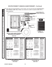
ROUTE/CONNECT CABLES & HAND PENDANT - Continued
LONG
POWER
CABLE
EXTERNAL
TOOTH LOCK
WASHER
TERMINAL
STUD
PROTECTIVE
COVER