


PATENTS PENDING
28
11921 Slauson Ave. Santa Fe Springs, CA. 90670 (800) 227-4116 FAX (888) 771-7713
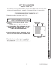
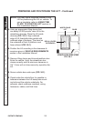
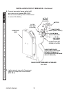
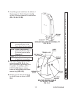
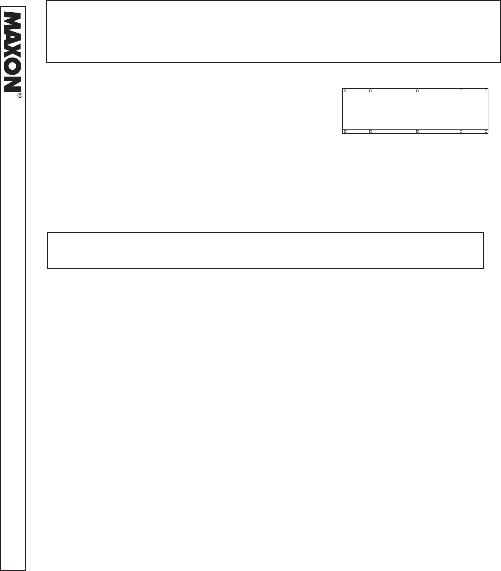
1. Use template (FIG. 27-1) or the base plate on the
Lift (FIG. 28-1, holes 1-10) to mark eight (8) to
ten (10) 7/16” mounting holes through the vehicle
fl oor. Before drilling holes in the vehicle fl oor, make
sure no wires and fl uid lines are too close to hole
locations. Drill holes 1, 2, 9, 3, and 4.
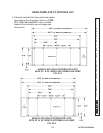
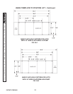
BASE PLATE BOLT
HOLE PATTERN
FIG. 28-1
12
3
4
56
7
8
9
10
BACK
FRONT
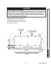
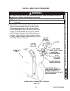
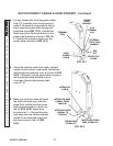
MOUNTING THE LIFT
NOTE: MAXON recommends using all 10 carriage screws (Kit items) to bolt Lift to
vehicle. A minimum of 8 screws or bolts and use of holes 1, 2, 3, 4 & 9 are
required for correct installation. Also, the 3 front holes should be selected to
give a symmetrical bolt pattern (i.e. holes 5,10, & 8 or holes 6,10, & 7).
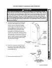
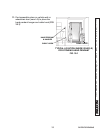
3. Temporarily secure Lift to vehicle with two mounting
bolts (Kit items), inserted through base plate holes 1
and 4, or holes 2 and 3 (FIG. 28-1). Use two lock
nuts and correct under-vehicle supports (Kit items) to
secure the Lift. Use instructions supplied with vehicle
installation kit to select the correct bolts, nuts and sup-
ports. Alternately, tighten the two bolts and nuts to 20
to 30 LBS.-FT.
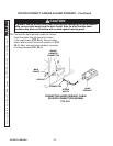
NOTE: Vehicle fl oor must meet the requirements shown at the beginning of the
VEHICLE REQUIREMENTS section in this Installation Manual.
2. Position Lift so holes 1-10 in the base plate (FIG. 28-1)
are aligned with the correct holes drilled in vehicle fl oor.