


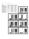

15
3
1
2
4
5
6
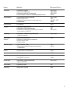
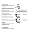
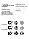
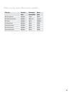
Hg50W
Hg100W
Adjusting the mercury vapour lamp
This adjustment is important for obtaining a uniform light spot
and good-quality fluorescence.
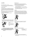
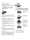
While adjusting the mirror image, do not project light
on to the electrodes for long periods (risk of explosion
through overheating)
The two electrodes are imaged as an extension of the plane
of symmetry of the discharge arc, but are difficult to see.
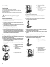
▶ Switch on the supply unit and wait for two or three minutes
• The100Wsupplyunitemitsawhistle
▶ Swing out the UV-light excluder (page 21)
• WorkwithouttheUV-lightexcluderisonlypermittedforadju-
stment, and then only for short periods
▶ Pull out the light stop (see page 16, MZ10 F and page 22,
Fluorescence module).
▶ MZ10 F: Turn the filter set in the beam path (page 16).
▶ Stereo-fluorescence module: Insert the excitation filter
(page 22).
▶ Mark a cross on a piece of paper and place it in the middle
of the illuminated spot
▶ Select the lowest magnification
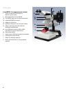
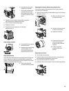
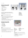
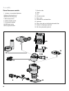
Figs. a: Bringing the discharge arc
into focus
Figs. b: Positioning the discharge arc
relative to the cross
Figs. c: Focusing and positioning the
mirror image of the discharge arc
• Thedischargearcisvisibleintheilluminatedspotandlies
at about 45° to the lines of the cross (fig. a)
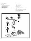
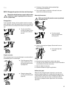
▶ Look into the eyepieces and focus on the cross
▶ Using your unaided eye, observe the discharge arc on the
paper and bring it into focus with the focusing knob (3) (fig. a)
▶ Using the positioning knobs (1 and 2), displace the discharge
arc (fig. b)
▶ Bring the mirror im age of the discharge arc into focus
with the knob (6) and use the knobs 4 and 5 to position it
symmetric ally relative to the original image (fig. c)
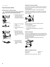
• Forthe50Wburner,thedischarge-arcimageandits
mirror image should touch
• Forthe100Wburner,thedischarge-arcimageanditsmirror
image should be superimposed.
▶ Using the focusing knob (3), readjust the illuminated field
• Theilluminatedfieldshouldnowbelarge,circularand
as uniform as possible
▶ Reposition the UV-light excluder correctly (page 21).