SECTION 5—WHEELCHAIR OPERATION
TDX
®
SI, TDX SI-HD 40 Part No 1154294
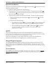
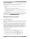
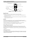
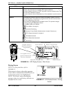
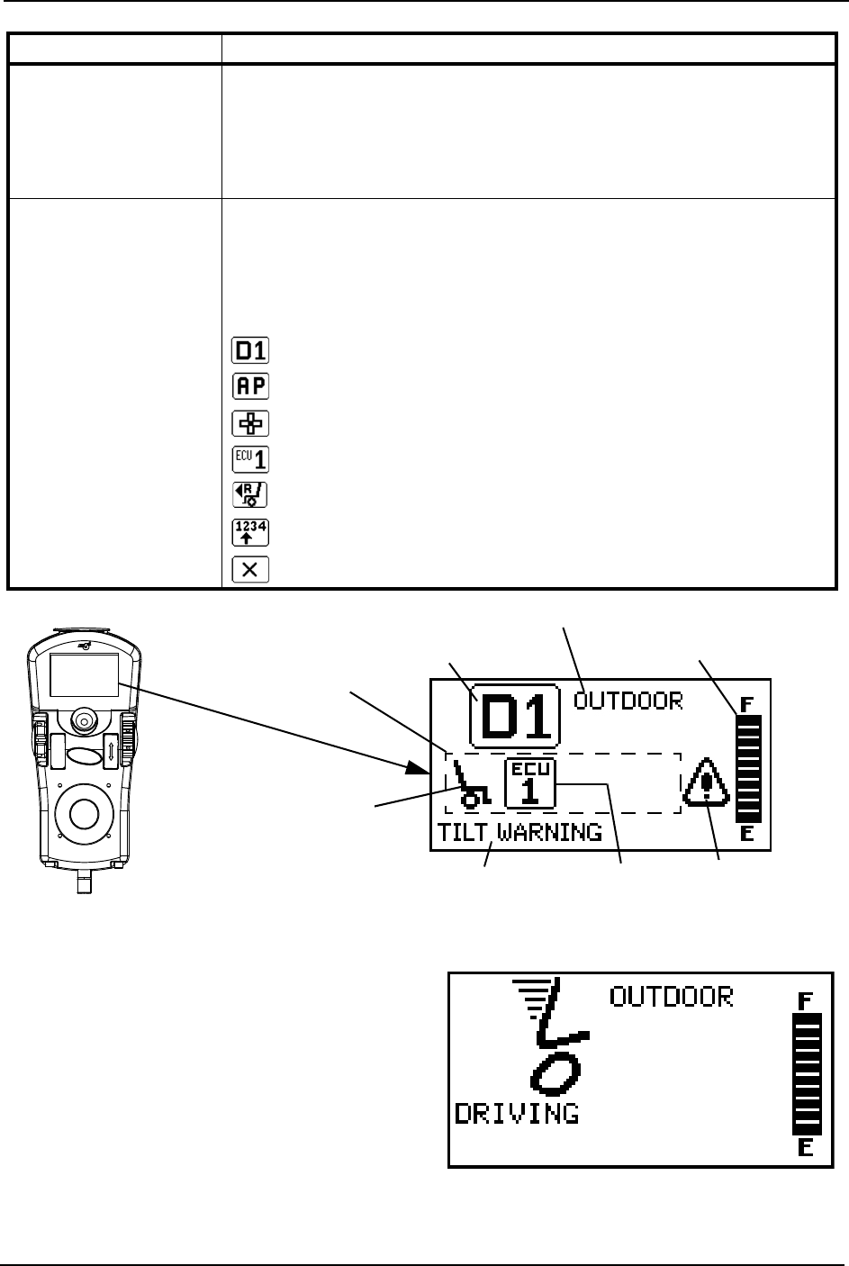
FIGURE 5.6 LCD Display Screens - Main Screen
Driving Screen
NOTE:Forthisprocedure,referto
FIGURE 5.7.
Thisscreenisshownwhentheoperator
issuesadrivecommandandtheDriveIcon
onthemainscreenwashighlighted.
NOTE:TheDrive’sname,warning/info
message,statusiconandbatteryindicatorare
displayedonthisscreen.
FIGURE 5.7 LCD Display Screens - Driving
Screen
STATUS INDICATOR The status indicator will show a “Warning” (exclamation point inside a triangle)
indicator when the chair has a condition that requires attention.
The status indicator will show a “STOP” sign when a serious condition exists. The
chair will not be allowed to operate.
The status indicator shows an Attendant Icon if the attendant’s override switch is
active.
MODES The dotted-box shows the area that contains the available “modes” in the cur-
rently selected drive. The modes are programmed for each drive and are based
upon the configuration of the chair.
These modes are highlighted when the Mode is active. The operator changes
modes by pressing the Mode Select Switch.
The available modes are as follows:
Drive Mode (1 through 4)
Automatic Positioning
Actuator Control Switch Mode (4-switch, 4-switch 2 levels, etc.)
ECU Output Activated (1 through 4)
RIM Mode Activated
Drive Select Mode Activated
No Driving
ITEM DESCRIPTION
Available Modes in
this Drive (Must be
Programmed)
ECU
Drive Indicator
Icon appears when a
joystick command will
drive the wheelchair
Battery Gauge Display
Status/Info Message Area
Status Indicator
Drive Profile Name


