


49
This Procedure includes the following:
Replacing Motor/Gearbox
MOTOR/GEARBOX PROCEDURE 13
M
O
T
O
R
/
G
E
A
R
B
O
X
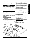
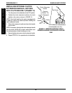
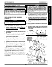
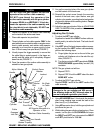
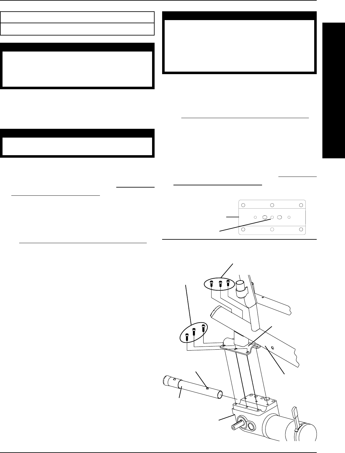
FIGURE 1 - REPLACING MOTOR/GEARBOX
Wheelchair
Frame
Long Socket
Screws (Apply
Loctite 242 and
torque to 60-
inch pounds)
Alignment
Hole
Motor Mount
Plate
Short Socket Screws
(Apply Loctite 242 and
torque to 60-inch pounds)
DETAIL "A"
Motor Mount Plate
Alignment Pin
Support Tube
Motor/Gearbox
(Standard Motor
Shown)
WARNING
After ANY adjustments, repair or service and BE-
FORE use, make sure all attaching hardware is
tightened securely - otherwise injury or damage
may result.
CAUTION
The longer socket screws must be positioned in
the mounting holes on the OUTSIDE of the wheel-
chair frame and the short socket screws must be
in the mounting holes on the INSIDE of the wheel-
chair frame. Otherwise damage to the gearbox
casting can result.
7. Use Loctite 242 and securely tighten the support tube
and motor/gearbox to the wheelchair frame with the
six (6) socket screws. Torque to 60-inch pounds.
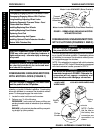
8. Reinstall the rear wheels onto the wheelchair. Refer
to
INSTALLING/REPLACING REAR WHEELS in
PROCEDURE 12 of this manual.
9. Reconnect the right and/or left motor connector to the
controller.
10. Repeat procedure for opposite side of the wheelchair,
if necessary.
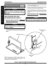
11. Reinstall the battery boxes. Refer to
INSTALLING/
REMOVING BATTERY BOXES in PROCEDURE 8
of this manual.
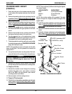
REPLACING MOTOR/GEARBOX
(FIGURE 1)
WARNING
The following procedure should only be per-
formed by a qualified technician.
NOTE: The following procedure can be followed for either
BASIC , STANDARD or 250 SERIES motor/gearboxes.
1. Remove the battery boxes. Refer to INSTALLING/
REMOVING BATTERY BOXES in PROCEDURE 8
of this manual.
2. Disconnect the right and/or left motor connector from
the controller.
3. Remove the rear wheels from the wheelchair. Refer
to
INSTALLING/REPLACING REAR WHEELS in
PROCEDURE 12 of this manual.
4. Remove the six (6) socket screws that secure the
motor/gearbox and support tube to the wheelchair
frame.
5. Reposition new motor/gearbox on wheelchair frame.
6. Position the support tube between the wheelchair
frame and the new motor/gearbox. Make sure the
alignment hole in the support tube is positioned with
the alignment pin on the motor mount plate.
NOTE: The alignment pin is the longest of the three (3)
pins and is located in the center of the wheelchair frame
motor mount plate. Refer to DETAIL "A" in FIGURE 1.
NOTE: When the alignment hole in the support tube is
positioned with the alignment pin on the wheelchair frame,
the anti-tipper wheels should be pointing down towards
the ground/floor.