


45
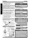
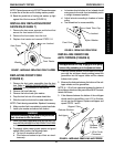
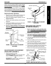
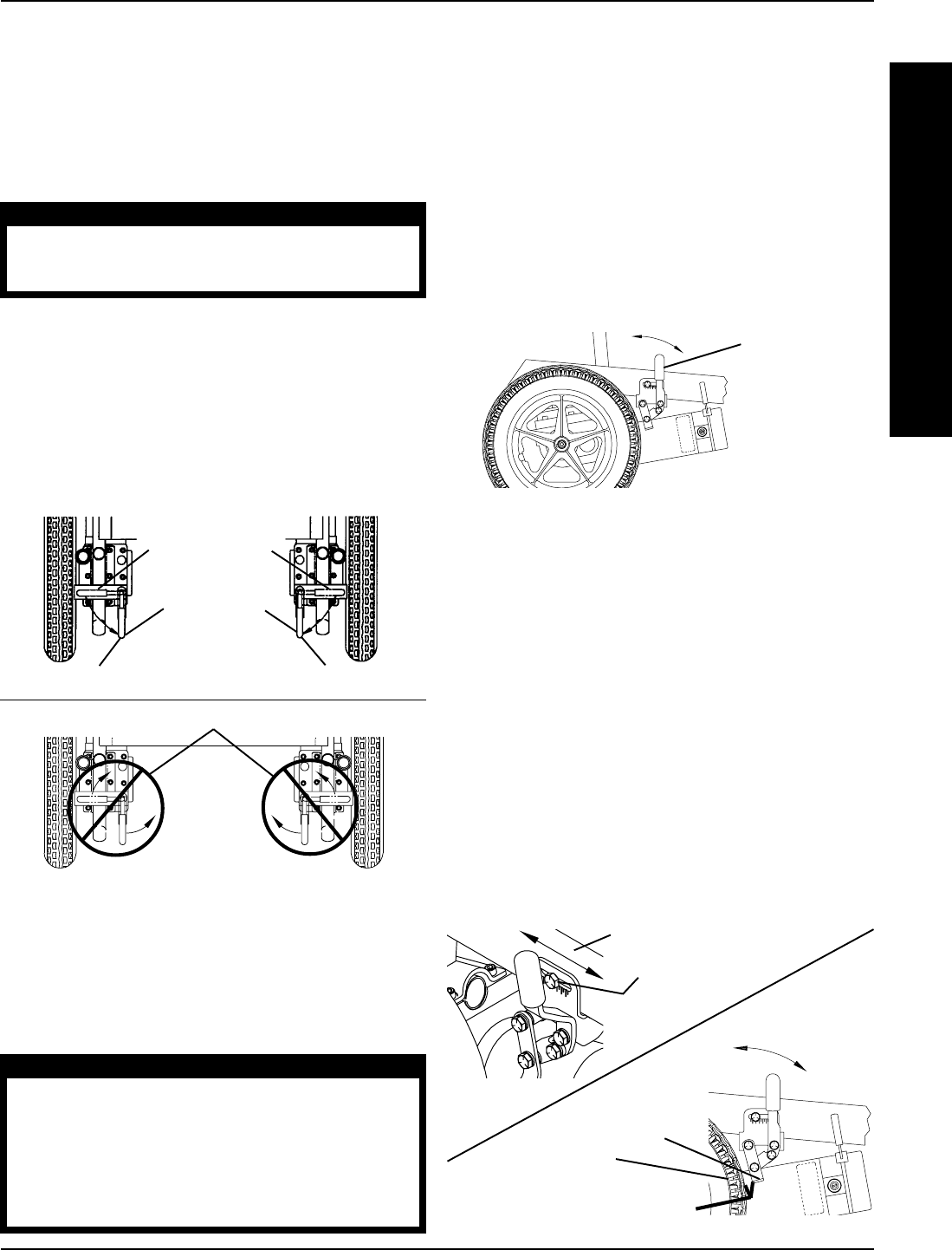
Wheel Lock
Shoe
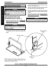
FIGURE 5 - INSTALLING/ADJUSTING WHEEL LOCKS
Rear Wheel
Hex Screw
Wheelchair Frame
5/32 to 5/16-inch
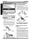
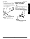
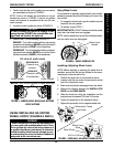
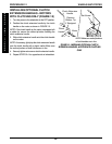
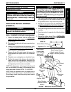
FIGURE 3 - DISENGAGING/ENGAGING MOTORS
WITH CLUTCHES
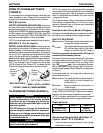
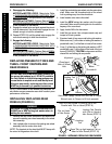
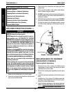
Wheel Lock
Handle
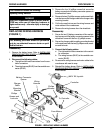
FIGURE 4 - USING WHEEL LOCKS
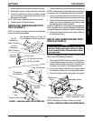
1. Confirm that the tabs on the battery box connectors
are assembled as shown in FIGURE 2.
NOTE: If tab on the battery box connectors is not as-
sembled as shown in FIGURE 2, remove the phillips
screws and locknuts to assemble the tab onto the con-
nector correctly.
2. Locate the clutch handles on motors (FIGURE 3).
CAUTION
If clutch handles are forced to engage in the
wrong direction (FIGURE 3), the motors will be dam-
aged and will need to be replaced.
3. Perform one (1) of the following (FIGURE 3):
ENGAGE - Turn clutch handles until they are pointing
towards rear of wheelchair. NEVER try to turn the clutch
handles towards the FRONT of the wheelchair.
DISENGAGE - Turn clutch handles until they are point-
ing towards rear wheels. NEVER try to turn the clutch
handles towards the INSIDE of the wheelchair.
USING/INSTALLING/ADJUSTING
WHEEL LOCKS* (FIGURES 4 AND 5)
WARNING
*Wheel locks are an OPTION on this wheelchair,
(you may order with or without wheel locks). Trans-
fer to and from the wheelchair in the presence of
a qualified healthcare professional to determine
individual safety limits. Invacare strongly recom-
mends ordering the wheel locks as an additional
safeguard for the wheelchair user.
Installing/Adjusting Wheel Locks
NOTE: Before adjusting or replacing the wheel lock as-
semblies, ensure that the tires are inflated to the recom-
mended psi on the side wall of tire.
1. Position the wheel lock on the wheelchair frame.
2. Loosely install the hex screw that secures the wheel
lock to the wheelchair frame.
3. Make sure wheel lock is disengaged from rear wheel.
4. Measure the distance between the WHEEL LOCK
SHOE and the REAR WHEEL.
5. Slide the wheel lock along the wheelchair until the
measurement is between 5/32 and 5/16-inches.
6. Tighten the wheel lock to the wheelchair frame.
7. Repeat this procedure for the opposite wheel lock.
W
H
E
E
L
S
/
A
N
T
I
-
T
I
P
P
E
R
PROCEDURE 12WHEELS/ANTI-TIPPER
Using Wheel Locks
The wheelchair is optionally equipped with a pair of inde-
pendently operated wheel locks located just in front of the
rear wheels.
1. To engage the wheel locks, grip the handle and push
forward to the lock position.
2. To release, reverse STEP 1.
IMPORTANT NOTE: DO NOT attempt to drive the wheel-
chair when the wheel locks are engaged.
NOTE: Use the wheel locks to hold the wheelchair when-
ever the motor locks are disengaged.
Clutch Handle
NEVER
Force clutch handles in these directions
ENGAGED
(Towards rear
of wheelchair)
Clutch Handle
DISENGAGED
(Towards rear
wheels)
TOP VIEW OF WHEELCHAIR