


40
E
L
E
C
T
R
O
N
I
C
S
ELECTRONICSPROCEDURE 9
This Procedure includes the following:
Preparing MKIV Joystick for Use
Disconnecting/Connecting MKIV Controller Motor
and Battery Leads
Repositioning MKIV Joystick
Removing/Installing MKIV Controller
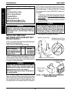
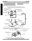
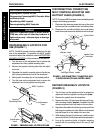
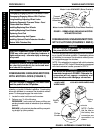
PREPARING MKIV JOYSTICK FOR
USE (FIGURE 1)
NOTE: The MKIV joystick is factory installed on the right
side of the wheelchair. To reposition the MKIV joystick
onto the left side of the wheelchair, refer to REPOSITION-
ING MKIV JOYSTICK in this procedure of the manual.
1. Turn the lever on the adjustment lock to release the
adjustment lock from joystick mounting tube.
2. Remove the joystick mounting tube from the adjust-
ment lock.
3. Reposition the joystick mounting tube so that the joy-
stick is facing towards the front of the wheelchair.
4. Slide joystick mounting tube to the desired position.
5. Turn the lever on the adjustment lock to secure the
adjustment lock to the joystick mounting tube.
Adjustment
Lock
Joystick
MountingTube
FIGURE 1 - PREPARING MKIV JOYSTICK FOR USE
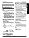
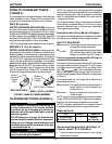
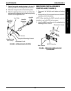
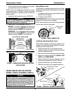
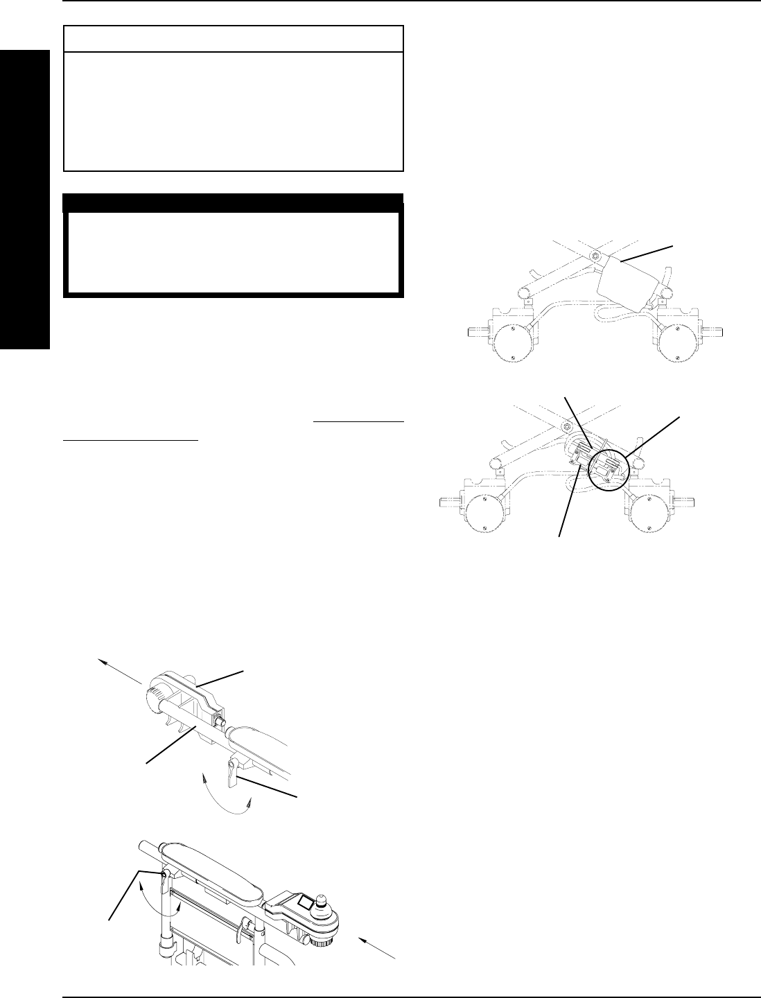
DISCONNECTING/CONNECTING
MKIV CONTROLLER MOTOR AND
BATTERY LEADS (FIGURE 2)
NOTE: To connect MKIV controller motor and battery leads,
reverse the following procedure.
1. Disconnect the fastening straps that secure the nylon
boot around the connected motor and battery leads.
2. Disconnect the controller left/right motor and battery
leads from leads secured to wheelchair with tie wraps.
Nylon Boot
Battery Lead
Leads From
Controller
FIGURE 2 - DISCONNECTING/CONNECTING MKIV
CONTROLLER MOTOR AND BATTERY LEADS
Left/Right Motor Leads
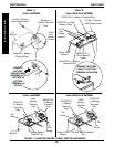
MKIV Joystick
Adjustment
Lock
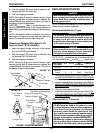
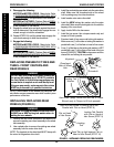
WARNING
After ANY adjustments, repair or service and BE-
FORE use, make sure all attaching hardware is
tightened securely - otherwise injury or damage
may result.
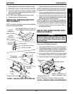
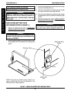
REPOSITIONING MKIV JOYSTICK
(FIGURE 3)
1. Turn the lever on the adjustment lock to release the
adjustment lock from joystick mounting tube (tube).
2. Remove the joystick from the wheelchair.
3. Remove the three (3) hex screws that secure the joy-
stick mounting bracket (bracket), threaded hole half
clamp and opened hole half clamp to the arm tube.
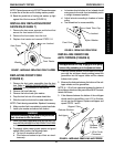
4. Reposition threaded hole half clamp and opened hole
half clamp on opposite arm tube. Make sure threaded
hole half clamp is on the inside of the arm tube.
5. While holding the two (2) half clamps, install front hex
screw into the two (2) half clamps and securely tighten.
6. Line up the mounting holes of joystick mounting
bracket with the mounting holes in the two (2) half
clamps.