


29
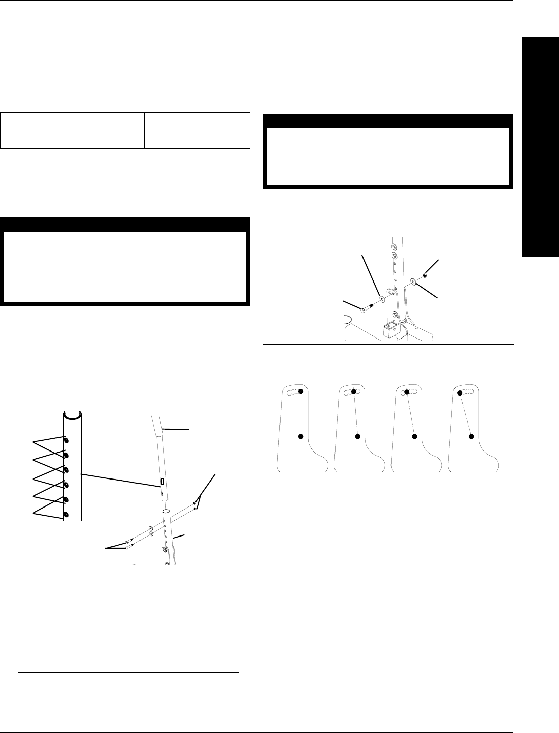
Locknuts
Hex Bolts (Apply
Loctite 242 and torque
to 75-inch pounds)
Bottom Half
of Back Cane
Top Half of
Back Cane
HOLE
PAIR #
5
4
3
2
1
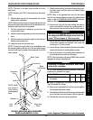
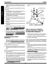
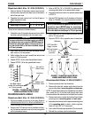
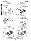
FIGURE 5 - CHANGING BACK HEIGHT -
WHEELCHAIRS BUILT AFTER 10/2000
Wheelchairs Built After 10/2000 (FIGURE 5)
1. Remove the two (2) hex bolts, washers and locknuts
that secure the top half of the back cane to the bottom
half of the back cane.
2. Reposition the back cane to one (1) of five (5) pairs of
height adjustment holes:
✪ ✪
✪ ✪
✪ HOLE PAIR # 1 2345
Back Height (in inches) 16 17 18 19 20
✪
Holes numbered from bottom to top for reference only.
(There are no numbers on the back canes.)
3. Reinstall the two (2) hex bolts that secure the top half of
the back cane to the bottom half of the back cane.
WARNING
The top and bottom half of the back canes MUST
be tightened securely together BEFORE using the
wheelchair, otherwise injury or damage may oc-
cur. Use Loctite 242 on the hex bolts and torque
to 75-inch pounds.
4. Use Loctite 242 on the hex bolts and torque into the
back canes to 75-inch pounds.
5. While holding the hex bolt, reinstall the locknut and
torque to 75-inch pounds.
6. Repeat STEP 5 for the other hex bolt and locknut.
7. Repeat STEPS 1-6 for the opposite back cane.
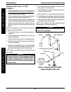
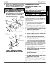
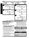
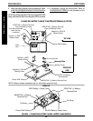
FIGURE 6 - CHANGING BACK ANGLE -
WHEELCHAIRS BUILT AFTER 10/2000
DETAIL "B"
90
O
95
O
100
O
105
O
TOP Hex Bolt
(Apply Loctite
242 and torque
to 75-inch
pounds)
Washers
Washers
Locknut
PROCEDURE 7FRAME
F
R
A
M
E
CHANGING BACK ANGLE
Wheelchairs Built After 10/2000 (FIGURE 6)
1. Flip the armrests up and out of the way. Refer to
USING/ADJUSTING FLIP BACK ARMRESTS in
PROCEDURE 5 of this manual.
2. Remove the TOP hex bolt, two (2) washers and lock-
nut that secure the back cane to the mounting plate
on the wheelchair frame.
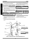
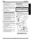
Wheelchairs Built Before 10/2000 (FIGURE 7)
1. Remove armrests from the wheelchair.
2. Remove the hex bolt, washer and locknut from the
top mounting hole of mounting plate and back cane.
NOTE: To keep inserts lined up for reinstallation onto wheel-
chair, install one (1) of the hex bolts through back cane
from the inside of the wheelchair to hold the insert in place.
3. Remove hex screw, washer and locknut from bottom
mounting hole of mounting plate and back cane.
4. Reposition back canes into the desired mounting holes
of the mounting plate to obtain a back angle be-
tween 85
o
and 105
o
in 5
o
increments.
5. Use Loctite 242 and torque hex bolts to 75-inch pounds.
6. Reinstall the armrests onto the wheelchair.
3. Refer to DETAIL "B" in FIGURE 6 to determine the
mounting plate hole for the desired back angle.
4. Reposition the back cane to the position determined
in STEP 3.
5. Reinstall TOP hex bolt, two (2) washers and locknut.
Refer to FIGURE 6 for correct hardware orientation.
WARNING
The back canes MUST be tightened securely to the
wheelchair frame BEFORE using the wheelchair,
otherwise injury or damage may occur. Use Loctite
242 on the hex bolt and torque to 75-inch pounds.
6. Use Loctite 242 on the hex bolt and torque the hex
bolt to 75-inch pounds.
7. Repeat STEPS 2-6 for opposite side of wheelchair.