


SECTION 9—WHEEL LOCKS AND ANTI-TIPPERS
Part No 1122134 61 Compass™SPT™
SECTION 9—WHEEL LOCKS AND
ANTI-TIPPERS
ƽ WARNING
After adjustments and before use make sure all attaching hardware is securely
tightened.
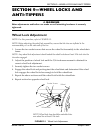
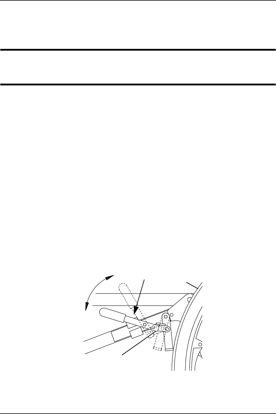
Wheel Lock Adjustment
NOTE: For this procedure, refer to FIGURE 9.1.
NOTE: Before adjusting the wheel lock assemblies, ensure that the tires are inflated to the
recommended p.s.i on the side wall of the tire.
1. Loosen the two socket screws that secure the wheel lock assembly to the wheelchair
frame.
NOTE: Any wheel lock adjustment should embed the wheel lock shoe at least 3/16-inch into the
tire when engaged.
2. Adjust the position of wheel lock until the 3/16-inch measurement is obtained for
correct wheel lock adjustment.
3. Securely tighten the two socket screws.
4. Engage the wheel lock and push against the wheelchair and determine if the wheel
lock engages the wheel lock shoe enough to hold the wheelchair.
5. Repeat the above sections until the wheel lock holds the wheelchair.
6. Repeat section for opposite wheel lock.
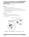
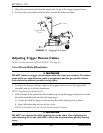
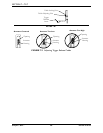
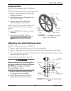
FIGURE 9.1 Wheel Lock Adjustment
Wheel
NOTE: Wheel lock shoe should be embedded into
rear wheel tire at least 3/16-inch.
Socket Screws
Wheel Lock