


SECTION 6—SEAT AND BACK
Lightweight, Standard and Heavy Duty Wheelchairs 42 Part No. 1114811
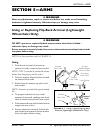
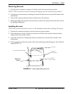
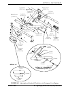
2. Remove the four button screws and locknuts that secure the two pivot links to the
wheelchair frame and crossbraces.
3. Remove the two button screws, locknuts and crossbrace saddle that secure the bottom
of the crossbrace to the wheelchair frame. Repeat for other crossbrace.
4. Remove the hex screw, coved washers, washers and locknut that secure the two
crossbraces together. Refer to Detail “B” of FIGURE 6.5.
5. Assemble the two new crossbraces together with the existing hex screw, coved
washers, washers and locknut. Securely tighten. Refer to Detail “B” of FIGURE 6.5.
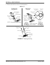
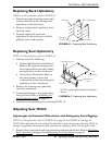
6. Determine the correct pivot link and mounting hole to use with the desired seat width.
Refer to Detail “B” of FIGURE 6.4.
7. Secure the pivot links to the crossbraces and wheelchair frame with the four button
screws and locknuts. Securely tighten.
NOTE: Position crossbrace saddle on wheelchair frame using the washer on the underside of the
wheelchair frame as a reference. See Detail “A” of FIGURE 6.5 for proper positioning of the
crossbrace saddle.
8. Reinstall the two button screws, locknuts and crossbrace saddle that secure the bottom
of the new crossbrace to the wheelchair frame. Refer to Detail “B” of FIGURE 6.5 for
hardware orientation. Repeat for opposite crossbrace. Securely tighten.
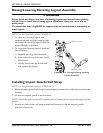
9. Install the new back and seat upholstery onto the wheelchair. Refer to Replacing Back
Upholstery on page 41 and Replacing Seat Upholstery on page 41.
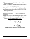
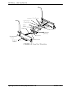
FIGURE 6.4 Lightweight and Standard Wheelchairs with Swingaway Front Riggings
SEAT WIDTH PIVOT LINK
16 - INCH
18 - INCH
20 - INCH
I
16-inch
18-inch
DO NOT USE
DO NOT USE
20-inch