A-4 38 Part No. 1110545
Wheelchair
Frame
UPHOLSTERY
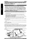
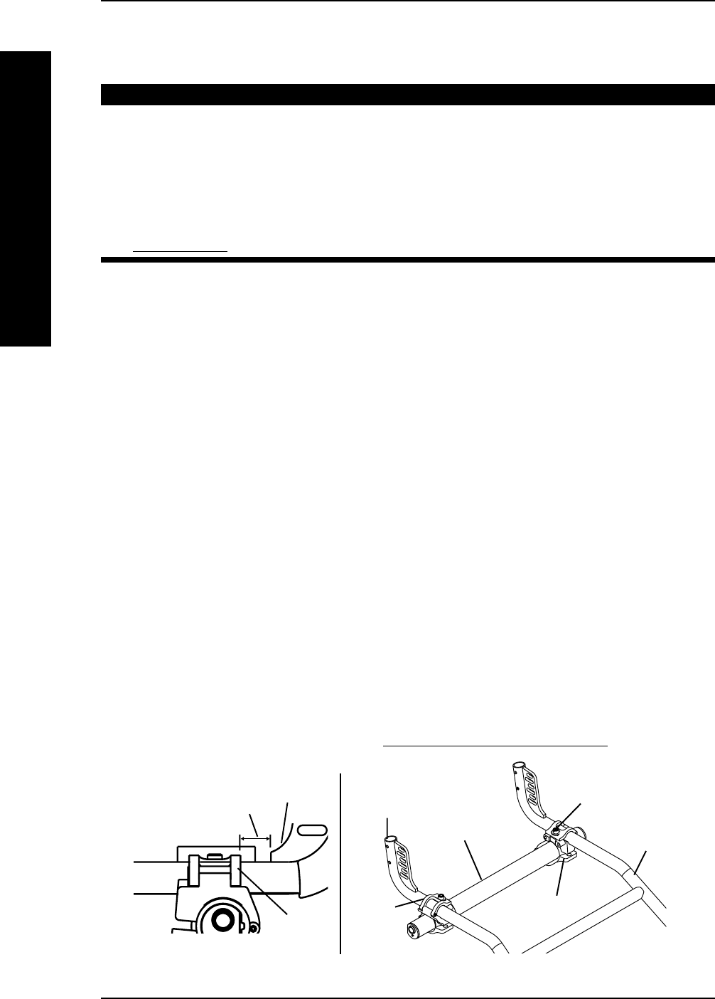
ADJUSTING WHEELBASE LENGTH (ADJUSTING CENTER
OF GRAVITY) (FIGURE 10)
WARNING
The position of the footrest, seat angle, back angle, seating system/
upholstery, caster size and position, rear wheel size and position, use of
anti-tippers, as well as the user condition directly relate to the stability of
the wheelchair. Any change to one (1) or any combination of the ten (10)
may cause the wheelchair to decrease in stability. EXTREME care MUST
be taken when changing the stability of the wheelchair. Refer to the chart
in
STABILITY in SECTION 1 of this manual.
NOTE: The camber bar is always mounted to the BOTTOM of the wheelchair frame.
1. Loosen, but do not remove the two (2) socket screws that secure the axle tube to
the wheelchair frame.
2. Position the camber clamps on the wheelchair frame at the desired position.
LENGTHENING THE WHEELBASE will increase the stability and maintain
standard maneuverability of the wheelchair.
SHORTENING THE WHEELBASE will increase the maneuverability, distribute
additional weight onto the rear wheels, and make the wheelchair less stable.
NOTE: The performance of the wheelchair will be affected if the camber clamps do not sit flush
on the wheelchair frame.
3. Securely tighten one (1) socket screw that secures the camber bar to the wheelchair
frame.
NOTE: Securely tightening one (1) socket screw at a time ensures that the camber clamps will sit
flush on the wheelchair frame.
4. Repeat STEP 3 for the opposite side of the wheelchair.
NOTE: The distance between the FRONT of the back post and the BACK of the top clamp on
each side of the wheelchair can be measured as an additional check to make sure the camber
clamps sit flush on the wheelchair frame (the measurements should be the same) (DETAIL "A").
5. Roll the wheelchair before using to make sure there is no excessive drag to either
side.
NOTE: If drag to either side occurs, refer to
DETERMINING TOE IN/TOE OUT in this section of
the manual.
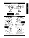
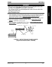
FIGURE 10 - ADJUSTING WHEELBASE LENGTH
(ADJUSTING CENTER OF GRAVITY)
SHORTENING
Axle Tube
LENGTHENING
Top
Clamp
Socket Screw -
Loosen But Do Not
Remove
Back Post
Camber Clamp
SECTION 4 FRAME
FRAME
DETAIL "A"
Measure this distance
Back Post
Top
Clamp


