


Part No. 1110545 35 A-4
SAFETY INSPECTION
15. Repeat STEP 7.
16. Perform one (1) of the following:
A. TOE IN/TOE OUT MEASUREMENT IS WITHIN ±1/8-INCH -
1. Proceed to STEP 17.
B. TOE IN/TOE OUT MEASUREMENT IS
NOT WITHIN ±1/8-INCH -
1. Repeat STEP 1.
2. Loosen the set screw on the RIGHT toe adjustment ring.
3. Repeat STEP 3.
4. REPEAT STEPS 12-16 until toe in/toe out measurement is within ±1/8 inch.
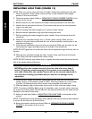
17. If desired, reposition camber inserts to the desired degree of camber. Refer to
REPOSITIONING CAMBER INSERTS (ADJUSTING REAR WHEEL CAMBER) in
this section of the manual.
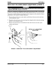
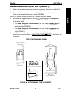
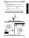
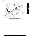
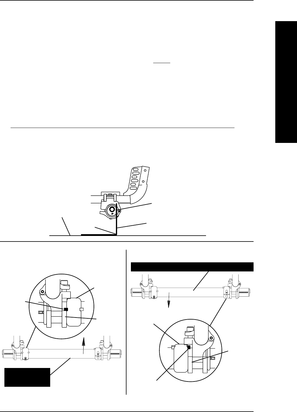
FIGURE 8 - ADJUSTING THE AXLE TUBE
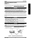
LOWER DEGREE OF CAMBER
Camber
Clamp
Axle Tube - Will
Rotate UP Only
LEFT Toe
Adjustment
Ring
LEFT Tab
Stopped
Against
LOWER
Edge of
Camber
Clamp
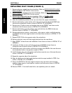
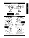
Camber
Clamp
RIGHT Toe
Adjustment Ring
RIGHT Tab Stopped Against UPPER Edge of
Camber Clamp
Axle Tube - Will Rotate DOWN Only
HIGHER DEGREE OF CAMBER
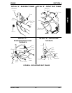
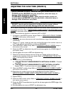
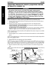
"L" Square
90°
Angle
Flat Edge of
Camber Insert
Ground/Floor
STEP 3
SECTION 4
FRAME
FRAME