


Part No. 1056953 51 9000 Series
USING/ADJUSTING THE WHEEL LOCKS
NOTE: For Using and/or Adjusting of Patient Oper-
ated Wheel Locks, refer to USING/ADJUSTING THE
PATIENT OPERATED WHEEL LOCKS in SECTION
8 of this manual.
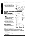
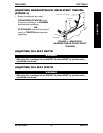
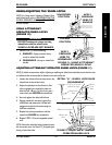
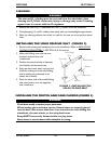
USING ATTENDANT
OPERATED WHEEL LOCKS
(FIGURE 10)
WARNING
DO NOT attempt to stop a moving
wheelchair with the wheel locks.
WHEEL LOCKS ARE NOT BRAKES.
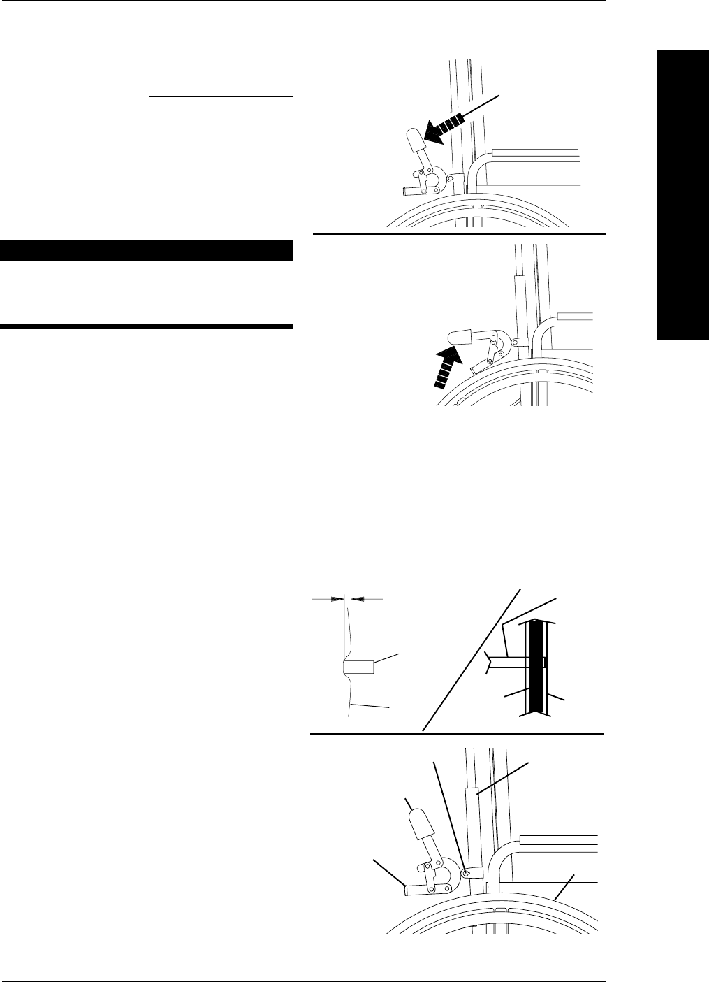
1. Perform one (1) of the following:
A. ENGAGE - Apply pressure down-
ward on wheel lock handle.
B. DISENGAGE - Lift up on wheel lock
handle.
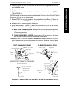
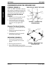
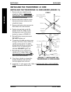
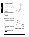
ADJUSTING ATTENDANT OPERATED WHEEL LOCKS (FIGURE 11)
NOTE: If wheels are pneumatic, before adjusting or replacing the wheel lock assemblies, ensure that the tires
are inflated to the recommended psi located on the side wall of tire.
1. Loosen the bolt and locknut that secure the
wheel lock to the recliner tube.
2. Adjust the position of wheel lock so that
when engaged, the wheel lock shoe em-
beds the tire 1/8-inch (3/16-inch for pneu-
matic tires) and HOLDS the wheelchair.
3. Securely tighten the bolt and locknut.
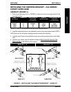
4. Engage wheel lock and push against the
wheelchair and determine if wheel lock
engages the wheel lock shoe enough to
hold the wheelchair.
5. Repeat the above procedures until the
wheel lock HOLDS the wheelchair.
6. Repeat STEPS 1-5 for the opposite wheel
lock.
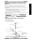
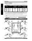
NOTE: Ensure the wheel lock shoe completely covers
the tire contact area. See Detail "A" for proper posi-
tioning of wheel lock shoe.
FIGURE 10 - USING ATTENDANT
OPERATED WHEEL LOCKS
APPLY
PRESSURE
HERE TO
DISENGAGE
LOCKED
POSITION
APPLY
PRESSURE
HERE TO
ENGAGE
UNLOCKED
POSITION
SECTION 9RECLINER
RECLINER
Wheel Lock Handle
Wheel Lock
Shoe
Bolt and Locknut
Rear Wheel
Recliner Tube
FIGURE 11 - ADJUSTING ATTENDANT
OPERATED WHEEL LOCK
DETAIL "A" - WHEEL LOCK SHOE
ENGAGEMENT
1/8-inch (3/16-inch
pneumatic tires)
Tire
Wheel Lock
Shoe
Tire
Section
Tire Contact
Area
Wheel
Lock
Shoe