


INFINITY
Residential Elevator
Specifications for Part 5.3 Compliance
Continued
4.15.3
Guides shall be bolted through the hoistway enclosure with back-up
plates, washers and nuts. Subject to architects’ alterations and approval.
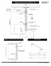
4.16 CAR SLING
4.16.1
Car sling shall be fabricated from steel members with adequate bracing to
support the platform and cab.
4.16.2
The buffer-striking member on the underside of the car must stop the
elevator before the jack plunger reaches its down limit of travel.
4.16.3
Guide shoes to be solid slipper type with polyurethane inserts.
4.17 WIRING
All wiring and electrical connections shall comply with applicable codes,
insulated wiring shall have flame retardant and moisture proof outer
covering and shall be run in conduit or electrical wireways. Traveling
cables shall be flexible and suitably suspended to relieve strain.
Part 5 - EXECUTION
5.1 EXAMINATION
All site dimensions shall be taken to ensure that tolerances and
clearances have been maintained and meet local regulations.
5.2 PREPARATION
Pre-inspect the construction and service requirements for "Work by
Others". These requirements will be included in drawings, diagrams,
engineering data sheets and special instructions before the work
commences.
4.10 CABLE
Minimum of two 3/8" (10 mm) IWRC Galvanized Aircraft Cables.
Minimum breaking strength of 14,400 lbs. each.
4.11 SAFETY DEVICE
A "slack/broken cable" safety device shall be supplied which will stop
and sustain the elevator and its rated load, if either of the hoisting cables
become slack or breaks. The safety device shall be resettable by the
operation of the elevator in the upward direction. A switch shall be
mounted in such a position as to sense the operation of the safety
device, and will open the safety circuit to the controller to prevent
operation of the elevator in either direction.
4.12 GUIDE YOKE
The 1:2 guide yoke/sheave arrangement shall be supplied with a
sheave, guide shoes, roller bearings and adjustable cable guards. The
sheave shall be finished with rounded grooves to fit the cables.
4.14 FINAL LIMIT SWITCH
The elevator shall be equipped with a final limit switch to cut off all power
to the elevator if the upper normal terminal stopping devices fail.
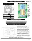
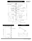
4.15 GUIDE RAILS AND BRACKETS
4.15.1
Steel 8lb/ft "T" guide rails and brackets shall be securely fastened to the
building structure.
4.15.2
Brackets shall securely hold the guides in a plumb and true position
regardless of car loading.
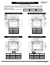
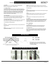
Rail Reactions
R1 = 304 LBF
R2 = 194 LBF
Rail reactions do not include safety factors.
Applicable safety factors must be considered
in hoistway design.
Rail Orientation to Support Wall
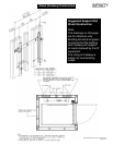
Typical Lower Rail Bracket Configuration
CPG-INFVER01 © 2004, Concord Elevator Inc.
Page 8 of 12