


INFINITY
Residential Elevator
Specifications for Part 5.3 Compliance
Continued
PART 4 – PRODUCT DATA
4.1 MANUFACTURER/PRODUCT
The elevator shall be the CONCORD INFINITY Residential Elevator
manufactured by Concord Elevator Inc. Toll Free (800) 661-5112 and
(905) 791-5555, Fax (905) 791-2222
Dealer Name ___________________________________
Number _______________________________________
Rated Load: 750 lbs. (340 kg.)
Nominal Speed: 36-fpm (0.18 m/s)
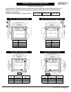
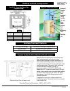
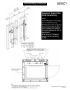
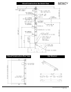
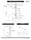
Car Dimensions: 36" W x 48" D (914 mm W x 1220 mm D)
Operation: Automatic
Gate Type: Horizontally collapsible, accordion style with 3 vision panels
Power Supply: 220 Volt, Single Phase, 30 Amps or 208 Volt, 3 Phase,
30 Amps
Travel Distance: 50 ft. (15.2 m) max __________________
Levels Served: (up to 5, max. 4 - SRE) ________________________
Number of Openings: Two (2) Maximum
Lighting Supply: 110 Volt, 1 Phase, 60 Cycle, 15 Amps
Jack Type: 1:2 Cable Hydraulic
Pump Type: Submersible with Variable Speed Valve Levelling
Device Type: Magnetic
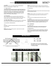
4.2 CAR ENCLOSURE
4.2.1 WALLS
1/2" (13 mm) Melamine panels and black anodized aluminum trim.
4.2.2 CEILINGS
Architectural white with four (4) recessed incandescent down lights.
4.2.3 FLOOR
Plywood sub-flooring.
4.2.4 HANDRAIL
Black painted oak handrail located on control panel.
4.2.5 EMERGENCY OPERATION
The elevator car shall be equipped with a battery-powered emergency
lowering device and alarm that can be actuated on the failure of normal
building power supply. Battery will be rechargeable type with an
automatic recharging system.
4.2.6 EMERGENCY LIGHT
The car shall be equipped with an integral emergency light that will
illuminate automatically in the event of a main power failure.
4.2.7 CAR OPERATING PANEL
Car operating panel shall consist of metal push buttons with halo
lighting for each landing, an emergency stop button, an alarm button
and a key switch. The key is removable in both the on and off position.
All mounted on a #4 finished stainless steel panel. Car station panel is
hinged.
4.2.8 DIGITAL FLOOR INDICATOR
Digital floor indicator located in the control panel will display the
location and direction of travel (floor number) of the elevator in the
shaft. (optional on SRE model)
4.2.9 CAR LIGHTING
The car lighting shall consist of four (4) low voltage recessed
incandescent down lights. The failure of one lamp shall not cause the
remaining lamp to extinguish.
4.2.10 AUTOMATIC LIGHTS
Overhead lights in the car compartment shall turn ON automatically when
the elevator door is opened and will stay on while the elevator is in use.
The elevator lights will shut off by a timer when the elevator is not in use.
4.3 DOOR LOCKS
Locks shall be electrically operated and electrically released at floor level
and will remain unlocked until hall or car call is placed. When released,
the locks’ lag member will drop down and close the electrical circuitry to
ensure the elevator cannot move unless the door is closed and locked (a
true interlock).
4.4 HALL CALL STATIONS
Provide a keyless hall call station with an illuminated call button and
stainless steel cover plate for each landing.
4.5 PLATFORM TOE GUARD
A platform toe guard shall be provided at each car entrance opening to
extend below the car entrance opening for safety.
4.6 LEVELING DEVICE
a) The elevator shall be provided with a 2-way leveling device, which
will maintain the car within 1/2" (13mm) of the landing.
b) Levelling device sensors shall be located in a position to
be inaccessible to unauthorized persons.
4.7 CAR GATE REQUIRED OPTION
Horizontally collapsible accordion style woodfold car gate with rattan
panels and three (3) clear acrylic vision panels car gate shall enclose
each car entrance.
4.8 HYDRAULIC POWER UNIT
a) The pump and motor shall be the submersible type installed
inside the oil tank.
b) The controller shall be integrally mounted on the power unit
frame and pre-wired and tested before shipment.
c) Control circuitry to be located at the top of the oil tank.
d) The power unit control valve shall be a variable speed
proportional valve type that includes all hydraulic control valving
inherently.
This valve shall incorporate the following features:
(i) Up and down acceleration and deceleration speed adjustment for
smooth starts and stops.
(ii) Smooth stops at each landing shall be an inherent feature of the
valve.
(iii) Adjustable pressure relief valve.
(iv) Manually operating 'DOWN' valve to lower elevator in an
emergency.
(v) Pressure gauge indicating in P.S.I. and Bars.
(vi) Gate valve to isolate cylinder from pump unit.
(vii) Negative pressure switch.
4.9 CYLINDER AND PLUNGER
4.9.1
The cylinder shall be constructed of steel pipe of a sufficient thickness
and suitable safety margin. The top of the cylinder shall be equipped with
a cylinder head with an internal guide ring and self-adjusting packing.
4.9.2
The plunger shall be constructed of a steel shaft of a proper diameter
machined true and smooth. The plunger shall be provided with a stop
electrically welded to the bottom to prevent the plunger from leaving the
cylinder.
CPG-INFVER01 © 2004, Concord Elevator Inc.
Page 7 of 12