


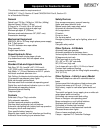
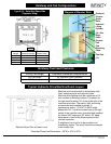
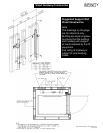

Elevator
Guide
Rails
Hydraulic
Lifting
Cylinder
3/8" Wire
Rope
Cable
Elevator
Cab
Cab
Operating
Panel
Cab Gate
Overhead
Diagram of Elevator Shaft
Pit
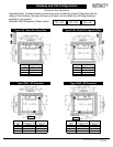
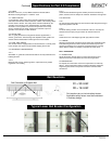
Hoistway and Cab Configurations
Type 5 (S) - Enter/Exit Same Side
(Opposite Sling)
INFINITY
Residential Elevator
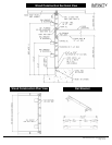
Clear Cab
Len
g
th
Finished
Hoistwa
y
Len
g
th
Side Entrance
Center Lines
48" 54 1/4" 27 1/8"
54" 60 1/4" 30 1/8"
60" 66 1/4" 33 1/8"
X X + 6 1/2" (X + 6 1/4") / 2
see chart
WIDTH
LENGTH
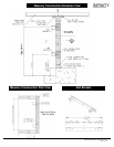
Hoistway Overhead Clearance
Infinity Cab Height Overhead Clearance Requirements
80" Cab Height 92" Minimum Clear Overhead
96" Cab Height 108" Minimum Clear Overhead
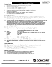
Typical Hydraulic Drive Machine Room Layout
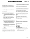
Machine room must be built in accordance with
local, state/provincial and national codes.
Machine room lighting shall be a minimum of 19
foot candles at working surfaces. The switch for
the light must be within 18" of the strike side of the
machine room door. The switch, light and wiring
are provided and installed by others. A
convenience outlet, 115 VAC 15 AMP single
phase with G.F.I. shall be located next to the light
switch in the machine room. provided and installed
by others. NEC requires a 30" wide x 36" deep
work space in front of the disconnects and the
elevator controller.
A telephone line circuit is to be provided and
installed by others. This circuit must be connected
to an outside line.
Machine Room Plan at Lower Level
Controller/Pump Unit Dimensions = 30"W x 16"D x 55"H
CPG-INFVER01 © 2004, Concord Elevator Inc.
Page 5 of 12