


INFINITY
Residential Elevator
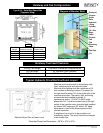
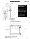
Drawing Notes
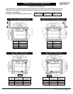
1 See Elevator Drawing for rail bracket spacing and pit depth.
2 Wall lateral support spacing:
- for 2" x 4" studs, use 6' -10" (2090 mm) max.
- for 2" x 6" studs, use 13' -6" (4120 mm) max.
3 Sheathing installation: install sheets vertically full width of shaft or min.
centred on rail brackets.
4 Connectors to resist horizontal load but allow vertical movement.
For Wood, use 2" x ¼" cap screw lag bolts.
General Specifications
G1 The design and construction of all work is to conform to the local applicable building code.
G2 Read these drawings in conjunction with all related architectural, mechanical, electrical, and
elevator drawings as well as any other contract documents.
G3 The wall drawings have been prepared using engineering principles and the design loads that are
applied by the elevator rails to the wall. However, the details and member sizes and the
attachments to the structure should not be construed as a complete design of the wall system.
The contractor and/or the project engineer is responsible to evaluate the other loads that are
applied to the wall from the floor or roof system and modify member sizes or connections as
required by their analysis.
G4 Do not scale the drawings.
G5 See elevator shop drawings for service loads (including dynamic effects)
which are: - horizontal load parallel to the wall = 194 lb.
- horizontal load perpendicular to the wall = 304 lb.
G6 Wood SPF NO 1/2 Mix
Concrete 3000 psi (20 Mpa) @ 28 days. If exposed use 5% to 7% air content.
A. Bolts ASTM A307
Mortar Type “S”
Masonry
Grout 2100 psi (14 Mpa) High Slump
Block 2100 psi (14 Mpa) on net area
G7 Wall to be installed plumb and square within 1/8" (3mm) of top and bottom of shaft.
G8 Wall lateral support spacing (H) selected for maximum horizontal deflection of H/360 from rail
loads.
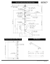
Wood Construction
W1 Separate wood from concrete with waterproof barrier or use pressure treated wood.
W2 Bridging Maximum Spacing: Load Bearing or Shear walls – 4' c/c
W3 Nail or screw sheathing at 6" c/c at edges and 12" c/c to other members.
Use 2.5" Standard Ardox nails or 2" #12 Screws.
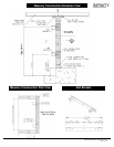
Masonry Construction
M1 All masonry construction to conform to applicable local standards
M2 Reinforce lintel blocks with 2-15m bottom bars unless noted.
M3 Provide continuous ladder type joint reinforcement at 16" (400) c/c.
Elevator Rail Support Wall
1-800-661-5112
www.concordelevator.com
ELEVATORS and LIFTS
®
CPG-INFVER01 © 2004, Concord Elevator Inc.
Page 12 of 12