


Parts -
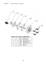
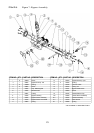
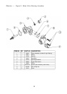
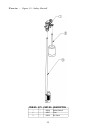
Figure 11 - Drain End Cap Assembly
ITEM NO.
QTY. PART NO.
DESCRIPTION
1
1
93808
O-Rinq
2
1
90268
Drain End Cap
3
1
H2086-3.0
Drain Line Flow Control
4
1
90267
Retainer
(1)
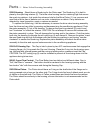
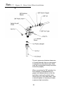
90268 Drain End Cap:
Seals the left opening on the Main Valve Body. The opening is sealed with
an 0-ring used as axial or "face" seal. The 0-ring sits in a groove in the End Cap. This groove must be
free of defects such as pits or scratches and also free of debris.
When assembling the End Cap to the
Valve Body, care should be taken to make sure that the 0-ring stays in the groove in the End Cap. If
misaligned, the 0-ring can become pinched and leak.
(2)
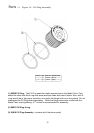
H2086 Drain Line Flow Control Button:
The Drain Line Flow Control Button (D.L.F.C.) maintains a
constant
(plus
or minus 10%) backwash flow rate at varying pressures. Care should be taken when
replacing FCB's to insure that the correct rate is being used for a particular model. Refer to Engineering
Specifications, pg. 13. The flow control button should be assembled with the lettering facing the retainer.
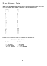
H2086 - 2.4*
H2086 - 3.0*
H2086 - 5.0*
H2086 - 7.0*
(3)
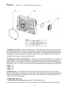
90267 Retainer:
The Retainer holds the backwash Flow Control Button in place. One side is
smooth and the other has a groove for a screw driver. When assembling the retainer to the Drain End
Cap, the retainer should be "screwed" in until it stops. If the retainer is not fully engaged, the Flow
Control may not function properly.
(4)
93808 End Cap 0-ring
90614 Drain End Cap Assembly
(contains all of the above items)
*The numbers shown after the Drain Line Flow Control Button Part # indicate the back wash flow rate in gpm.
32