


Page 9
MSP900SH
Installation, Operation & Maintenance Manual
IP2040/IM, Rev. AA
May 2007
3.4 Additional components in the two wire loop
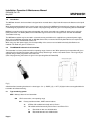
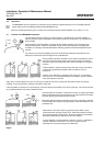
3.4.1 Safety barriers – installation of the transmitter in a hazardous area
When used with the Mobrey Measurement Control Unit Series MCU900, NO additional safety barriers are required as the
output from the control unit is Intrinsically Safe (refer to manual IP2030/IM supplied with the control unit for full details)
If powering the transmitter from any other power supply, it is the responsibility of the user to ensure a suitable Intrinsically Safe
barrier is fitted in the safe area.
The barrier must be chosen such that it’s output parameters Uo, Io and Po are less than Ui, Ii and Pi of the MSP900SH
transmitter.
For the MSP900SH transmitter, Ui = 30V, Ii = 120mA and Pi = 0.82W.
In addition, the sum of the capacitance and the inductance of the transmitter and any extra cable fitted must not exceed the
maximum specified for the barrier chosen.
For the MSP900SH transmitter with 50m of factory fitted cable, Ci = 5nF and Li = 27mH
Suitable barriers include the MTL products 706, 706S, 787, and 787S.
3.4.2 Lightning / surge protection and other loop devices
It is allowable to fit loop powered or separately powered devices in the two wire loop provided that the transmitter receives a
minimum voltage of 12V dc at 21 mA loop current.
It is the responsibility of the user to ensure any loop devices, if mounted in the hazardous area, carry the requisite hazardous
area certification and do not cause the system parameters to exceed those of the safety barrier (or MCU900).
If the area is prone to lightning strikes or voltage surges, fitting of a supressor device is desirable between the transmitter and
the control unit.
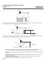
3.5 Wiring to allow HART communication
When used with the Mobrey Measurement MCU900 Control Unit, there is no need to install an external load resistor in the
loop as there is a suitable resistor built in to the Control Unit.
If it is intended to use HART digital communications with the MSP900SH transmitter, a 250Ohm 0.25W load resistor must be
installed in the loop.
If the transmitter is being supplied through a safety barrier, ensure the type chosen will pass HART/SMART information.
Once installed, a HART communicator can be connected across the load resistor, or across the loop at any point downstream
of the load resistor.
It is the responsibility of the user to ensure that any HART communicator used in the hazardous area is suitably certified for
that area.
3.6 Using the MSP900SH transmitter with an MSP90 Series controller
Although the MSP900SH transmitter is designed for use with the new MCU900 Series control units, there are many thousands
of MSP90 Series control units in the field with which it may be used.
It is important to note that the MSP90 Controller was normally used with an MSP90 style ultrasonic transducer, with the
controller supplying a voltage pulse to the transmitter and then interpreting and processing the return echo.
The MSP900 transmitter works in a different way, as it performs all processing in the transmitter itself, requiring only a loop
power connection to the control unit.