


Page 10
MSP900SH
Installation, Operation & Maintenance Manual
IP2040/IM, Rev. AA
May 2007
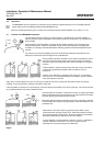
3.6.1 Wiring
When connecting the MSP900SH transmitter to an MSP90 Series control unit, different terminals are used in the control unit.
If connected, disconnect the existing MSP90 type transducer. These terminals are not used with the new MSP900SH type
transmitters.
Connect the MSP900SH screened and twisted pair cable to the current input terminals of the MSP90 Controller as follows:
MSP900SH wire Wall mount controller type
MSP90 - 11- C
Panel mount controller type
MSP90 - 61* - C
Red Terminal 18 : I in Loop Power+ Terminal 18 : I in Loop Power+
Black Terminal 14 : 4-20mA I in+ Terminal 8 : Current in+
Important note when the transmitter is located in a hazardous area:
If the MSP900SH transmitter is located in a hazardous area, it is the responsibility of the user to ensure that a suitable
Intrinsically Safe barrier is fitted in the safe area.
The barrier must be chosen such that it’s output parameters Uo, Io and Po are less than Ui, Ii and Pi of the MSP900SH
transmitter.
For the MSP900SH transmitter, Ui = 30V, Ii = 120mA and Pi = 0.82W.
In addition, the sum of the capacitance and the inductance of the transmitter and any extra cable fitted must not exceed the
maximum specified for the barrier chosen.
For the MSP900SH transmitter with 50m of factory fitted cable, Ci = 5nF and Li = 27uH
Suitable barriers include the MTL products 706, 706S, 787, and 787S.
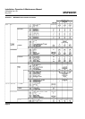
3.6.2 Programming the MSP90 Series control unit to operate with the MSP900SH transmitter
The MSP900SH is a transmitter and will need to be programmed to give a 4-20mA signal proportional to the level in the tank.
(See Section 5 of this manual)
On the MSP90 control unit :
Set P39 to 7. This sets the MSP90 control unit to current input mode.
Set P03 to the value, in metres, corresponding to the range of the 4-20mA output of the MSP900SH transmitter.
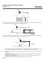
In a tank or sump of depth 8.5m, you will most likely have programmed the MSP900SH to give 4-20mA over the range 0.3m to
8.5m. P03 in the MSP90 control unit will therefore need to be set to 8.2.
P21 is a parameter which is used to convert level measurement to contents measurement. Where the vessel is a simple tank
or sump and the readout is required to be level, leave P21 set to 0.
If it is required to give a readout in contents, P21 should be set dependant upon vessel shape - refer to the MSP90 controller
manual.
A typical example is given in Appendix 2 of this manual.
Refer to the manual supplied with the MSP90 Control unit for full programming details of the MSP90 control unit if in any
doubt.
4.0. Maintenance
There is no routine maintenance required for the MSP900SH other than an occasional check to ensure that the front face of
the transmitter is clean and that the wiring is in good condition.