


Page 8
MSP900SH
Installation, Operation & Maintenance Manual
IP2040/IM, Rev. AA
May 2007
• In many installations, the use of a calibration device is mandatory. Mobrey Measurement offer the MSP-HVD for this
purpose, details on request.
In order to minimise measurement uncertainties when a calibration device is installed, it is recommended that the
calibrated range should be kept to a realistic minimum. i.e. max flow plus 10mm. Ensure that the target plate of the
calibration device does not fall within the 300mm blanking distance of the transmitter.
All calibrations should be derived to suit as installed conditions.
If you are in doubt about any aspect of transmitter installation, contact Mobrey Measurement (Service Division)
who will be pleased to advise.
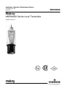
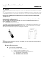
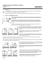
3.2 Mounting the transmitter above the liquid surface
The transmitter is supplied with a purpose made 316 Stainless Steel mounting bracket which should be used to mount the
transmitter over the liquid surface.
The bracket is designed to fit over the 1” threaded neck of the transmitter and is retained by a locknut.
IMPORTANT : Never suspend the transmitter by the cable.
Use a chain or wire through the hole provided in the bracket, which is shaped to ensure that the transmitter will hang
perpendicular to the liquid surface.
Check that the material of the chain or wire is corrosion resistant to the liquids and any vapours present.
Alternatively, the bracket may be bolted to a suitable cross member above the liquid surface. Ensure that the transmitter is
perpendicular to the liquid surface to maximise the return echo size.
Check that the maximum liquid level will not encroach into the 0.3m blanking zone of the transmitter.
Note: To aid alignment, the echo size / signal strength can be displayed on the MCU900 control unit or on a suitable HART
compliant handheld. Refer to IP2030/OM for full details.
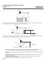
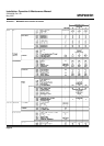
3.3 Wiring
The transmitter is supplied with a factory fitted length of PVC sheathed two core shielded cable which should be neatly run
back to the control unit or a suitable local IP65 junction box.
The transmitter cable cores are identified as follows :-
Red 24V dc
Black 0V dc
Screen Earth : must be connected to an Intrinsically Safe Earth in the non-hazardous area if the transmitter is
installed in a hazardous area.
Connect to a standard earth if the transmitter is not in a hazardous area.
The cable may be cut to length on site or may be extended using an IP65 junction box and suitable extension cable up to a
total length of 3000 m.
Where the transmitter is installed in a hazardous area, it is the responsibility of the user to ensure that the cable parameters of
the total length of cable used together with the parameters of the MSP900SH are less than the safety parameters of the safety
barrier (or MCU900 Control Unit if used instead) . See section 3.4 .
Multicore cable may be used provided that each pair within the multicore has a separate shield.
As good instrumentation practice, avoid tracking the cable with other cables which carry high voltages if possible.