


Page 5
MSP900SH
Installation, Operation & Maintenance Manual
IP2040/IM, Rev. AA
May 2007
3.0 Installation
The MSP900SH may be mounted in a hazardous area provided it is supplied through or from a suitably protected
power supply (such as the Mobrey Measurement MCU900 Series).
Refer to the safety parameters given in section 2.2 and safety instruction leaflet IP2040/SI (-A), 71097/1131 (-U).
3.1 Location of the MSP900SH transmitter
The transmitter must be installed in a location where it is protected from ultraviolet radiation, in
order to prevent long term degradation of the plastics used in its construction e.g. shrouded from
direct sunlight.
Correct location of the transmitter is essential for the reliable operation of any ultrasonic level
measurement system. Whilst the transmitter may be site tuned to deal with most application
conditions, it is strongly recommended that the following guidelines should be adopted wherever
relevant.
For maximum accuracy and stability of the level measurement reading the transmitter should
always be shrouded from direct sunlight and any radiated heat.
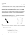
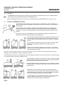
The transmitter should be mounted as near vertical as possible to ensure
a good echo from the liquid surface and maximum echo size received.
The beam angle (to the half power point) of the transmitter is 12 degrees
inclusive.
If the transmitter is located near the side of the tank or well, there will be
no false echo generated provided the wall is smooth and free of
protrusions.
However, there will still be a reduction in the echo size. To avoid large
echo size loss, it is recommended that the transmitter never be mounted
closer than 300mm to the wall.
Fatty, dirty or viscous liquids can cause a “scum line” to build-up on the tank or well wall. Avoid false echoes from this by
enabling “scum line prevention” software in the MCU control unit.
If the transmitter is mounted in an enclosed tank, avoid mounting the transmitter in the centre of the tank roof as this could act
as a parabolic reflector and create unwanted echoes.
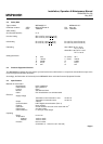
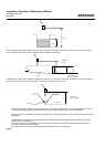
If the transmitter is mounted in a stand-off or nozzle, it is always preferable
that the transmitter face be at least 5mm proud of the stand-off such that it
protrudes beyond the stand-off and into the tank.
Remember that the minimum operating range of the transmitter is 300mm.
The transmitter will not detect any liquid surface closer than 300mm to the
transmitter face.
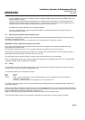
Obstructions in the tank or well may generate echoes which can be
confused with the real liquid surface echo. Obstructions within the beam
angle generate strong “false-echoes”; wherever possible, the transmitter
should be positioned such that false echoes are avoided.
To avoid detecting unwanted objects in the tank or well, it is advisable to
maintain a distance of at least 0.11m from the centre line of the
transmitter for every metre range to the obstruction.