


Page 6
MSP900SH
Installation, Operation & Maintenance Manual
IP2040/IM, Rev. AA
May 2007
3.1.1 General considerations
• The MSP900SH transmitter complies with the European Directive for Electro Magnetic Compatibility (EMC) Class B.
It is not advisable to mount the transmitter in close proximity to a source of electrical noise such as a variable speed
drive or other high powered electrical device.
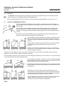
3.1.2 Liquid surface conditions
• Foaming liquids can reduce the size of the returned echo as foam is a poor ultrasonic reflector. It is always preferable
to mount an ultrasonic transmitter over an area of clear liquid, such as near the inlet to a tank or well. In extreme
conditions, or where this is not possible, the transmitter may be mounted in a vented stilling tube provided that the
inside bore of the stilling tube is at least 100 mm and is smooth and free from joints or protrusions. It is also preferable
that the bottom of the stilling tube does not become uncovered, thus preventing the ingress of foams.
• Beware of mounting the transmitter directly over any inlet stream.
• Liquid surface turbulence is not normally a problem unless it is excessive. In most cases, the effects of turbulence are
minor, with excessive turbulence being catered for by fine tuning the transmitter on site if necessary.
3.1.3 In-tank / well effects
• Stirrers or agitators can cause a vortex. Always try to mount the transmitter off-centre of any vortex to maximise the
return echo.
As stirrer blades become uncovered they will create echoes as they pass through the ultrasonic beam. The transmitter
can be tuned to ignore these false echoes on site.
• In non-linear tanks with rounded or conical bottoms, always mount the transmitter off-centre. In some cases, it may be
desirable to install a perforated reflector plate on the tank bottom directly under the transmitter
centre line to ensure a satisfactory return echo.
• Avoid mounting the transmitter directly above any pumps in the well as the transmitter will detect the pump
casing as the liquid falls away. If this is not possible, fine tuning on site may be required to ignore echoes
from the pump casings.
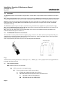
• If the well is subject to flooding, it is advisable to fit the transmitter with a submersion shield. Whilst the
transmitter will of course stop working whilst covered with liquid, the transmit face will be protected from
contamination by an air lock inside the shield.
3.1.4 Open Channel Flow installations
There are normally two distinct parts to an open channel flow measurement system; the primary element (flow structure) and
the secondary element (Head measurement instrumentation).
For accurate open channel flow measurement, both parts of the system must be installed accurately.
This manual explains some key aspects of the installation of the secondary element, in this case the ultrasonic transducer.
For full details of the installation of a primary element such as a flume or weir, reference should be made to the relevant British
(BS3680) or International standard.
In the United Kingdom, Mobrey Measurement offers a complete installation and commissioning service for open channel flow
measurement systems. For further information contact the sales office and/or refer to Mobrey Measurement’s ‘The Guide’.
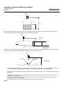
* Positioning of the transmitter is critical and should be the correct distance upstream from the flow structure as stated in
BS3680 e.g. a distance of 4 to 5 times hmax for a thin plate weir or 3 to 4 times hmax for a flume.
For optimum accuracy. the front face of the sensor should be positioned at a height that is at least equal to the maximum flow
depth plus the blanking distance of the transducer. A minimum distance of 310mm is recommended.