


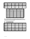
(I-0320--.doc/7)
7
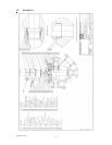
with the #6 well connection. This allows for the installation of the connector pin. Note that
installing the pin may require electrical power so that the upper section of the connector can be
rotated to align the bolt hole.
2. Install the lower section of the connector onto the stem flat. Orient the lower section of the
connector so that the indented mark is visible between the flats.
3. Install the two studs (1/2NC) diagonally opposite one another (180° apart).
4. Lower the actuator assembly over the studs, placing the indicator plate over the studs. Lower the
actuator assembly until it rests on the bonnet.
5. Install the two bolts (1/2NC X 1.25LG) to secure the assembly to the bonnet.
6. Install the lower nuts on the studs.
7. Tighten all bolts and nuts finger tight only.
8. With the connector sections aligned, install the connector bolt. Note that this may require
electrical power to rotate the connector and align bolt holes.
9. Install the spacers, indicator plate, and upper nuts on the studs. Leave the nuts loose, to be
tightened later when alignment is completed (step 11, below).
10. Wrench tighten the two bolts and lower nuts.
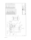
NOTE: Refer to electrical drawings and wiring diagrams for electrical power terminal connection
and motor voltage.
11. After connecting power to the motor, rotate the plug two revolutions to align the connectors.
Visually check for any binding and adjust as necessary. After ensuring correct alignment, wrench
tighten all bolts and nuts.
B. HOME PORT CALIBRATION (I-0168/RD-00232 Section H)
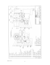
1. Using the JOG button, align the connector sections to install the connector bolt and tighten the
connector set screw.
2. If possible, remove the blind flange on the home port (port #8) and use the JOG button (tap briefly
for fine movement of the plug) on the controller circuit board to “fine tune” the plug seal/port
alignment.
3. Follow the procedure in the Multiport Electronic Controller Manual for home port calibration (set
zero).
4. When finished, align the hex corner of the lower connector with the appropriate slot on the
indicator plate. The pointer should also line up with the slot on the indicator plate.
5. If the unit has the optional local control push button station, select step mode and press the button.
The plug should move automatically to the next available port and slowly step into position.
Verify this by observing the hex connector and the slot in the indicator plate.
C. MULTIPORT ELECTRONIC CONT
ROLLER SET UP
Refer to the MEC service manual I-0168 for detailed instruction on:
1. Disabling port positions (I-0168 Section I).