


(I-0320--.doc/12)
12
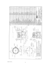
NOTE: An index mark on one flat on the square end of the plug (130) indicates port position. Install
the connector so that the index mark is visible.
4. Install the indicator (188) on the upper connector (410) using the nut (192). Ensure that the
indicator is aligned with the index mark on the square end of the plug.
5. Place the upper connector (410) on the lower connector with the setscrew (413) started but without
the connector bolt and locknut.
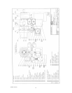
6. Install the speed reducer (426) onto the pedestal with the key (418) and four bolts (432),
lockwashers (436), and nuts (434).
7. Install the motor (438) onto the speed reducer with four bolts and lockwashers. Ensure that the key
is in place before aligning and tightening the motor mounting bolts (refer to motor and gear
reducer product info for specific installation and maintenance instructions).
8. Check for free rotation between the connector halves to confirm shaft alignment. This can be done
by turning the gear reducer by hand (or by using the electric motor) with the connector parts and
bolts loosely installed. Adjust the position of the connector halves if necessary.
NOTE: Use caution and keep hands away from all rotating parts if operating the electric motor to
check alignment.
9. Tighten all mounting bolts and nuts
10. Install and tighten the lower connector bolt and locknut and tighten the setscrew (413).
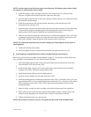
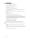
B. Local Stepping Command Electrical Conduit, Switchpak Pedestal, and Connector
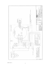
Refer to the typical electrical assembly drawing AB0463 on page 16. Note that the assembly details may
vary according to local regulations (i.e. use of cable instead of conduit).
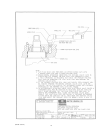
1. Set the Switchpak pedestal (448) on top of the speed reducer body and install four studs (452),
four lockwashers (453) and four nuts (454).
2.
3. Install the Switchpak connector (457) on the speed reducer shaft followed by the Switchpak
coupling (455) and the Switchpak coupling adapter (459).
4. Install the Switchpak (300) onto the Switchpak pedestal.
5. Install the four Switchpak bolts (458) and lockwashers (462).
6. Off the Switchpak pedestal assemble the push button station (350), local/remote switch (357), and
jog push button (356). Loosely install the push button station bolt (351), lockwasher (354), and nut
(352). If required, use the spacer (358) to fill the gap between the pushbutton station and the
Switchpak pedestal.
7. Install all wiring, conduit, and seals according to the electrical diagram and local regulations.
8. With connector parts loosely installed, rotate the shaft (either by hand or using the motor) and
check for proper alignment of the connector halves. Adjust if any binding is detected.
9. Tig
hten
all mounting bolts, nuts, and setscrews.
NOTE: Ensure that the connector setscrew seats against the flat section of the Switchpak shaft.