


(I-0320--.doc/11)
11
3. Turn the plug (130) at least one complete revolution while checking for smooth movement. If the
plug seal assembly (142) is binding at inlet ports when the plug is rotated, the plug seal assembly
or the seal wave springs (140) are not in their proper position(s). See disassembly procedure
below, if required.
4. Install the two bonnet vent plugs (176).
5. Perform any required leakage test(s).
VI
MULTIPORT DISASSEMBLY
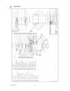
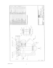
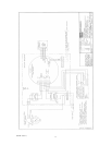
Refer to typical multiport assembly drawing AB0461 on page 14, and the multiport cutaway drawing
AB0462 on page 15.
NOTE: The bonnet can be removed with the motor and gearbox still attached as one unit. When
doing so, place a reference mark on the plug and connector before removal to ensure that they are
replaced in the same position when the bonnet, motor, and gearbox are re-installed.
1. Ensure that both the group and test pressures are zero before proceeding.
2. Open a home test port for access to the seal assembly. Turn the seal adjusting nut (138) clockwise
until solid (viewing toward plug centerline) in order to release the spring load from the plug seal
assembly and provide clearance for the scraper in the body.
3. Remove the bonnet nuts (182) and studs (180). Lift the bonnet vertically until it is clear of the plug
and body. Lifting eyes can be installed in the jacking screw holes provided in the bonnet for
some NPS 3" (3/4" NC) and NPS 4" (1/2" NC) Multiports. Set the bonnet aside.
4. Remove the plug (130), complete with all seal components, from the multiport body.
5. Disassemble the plug and plug seal and inspect all components. Reassemble following Multiport
Assembly procedure. The seal can be removed using the adjusting tool as follows:
i) Insert the tool into the seal adjusting nut and turn it counterclockwise until it disengages from
the final thread on the plug/rotor body.
ii) Use the tool as a slide hammer on the back of the seal adjusting nut to pull the seal assembly
out of the plug/rotor body.
6. Removal of the bearing cup from the bonnet may require the use of a square stem puller and/or dry
ice (to shrink and loosen the bearing cup).
VII
ACTUATOR ASSEMBLY
A. Pedestal, Connector, Speed Reducer, and Motor
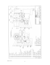
Refer to typical assembly drawing AB0461 on page 14 and the typical controller assembly drawing
AB0463 on page16.
1. Set the speed reducer pedestal (400) in place. Align motor for correct orientation.
2. Install two bolts (404), two lockwashers (406), two spacers (401), two studs (403), and four nuts
(405) with the indicator plate (402). The two bolts must be installed opposite each other (180°
apart) so that the indicator plate can be mounted on the studs and spacers.
3. Install the lower connector (408).