


Instruction Manual
Appendix E Rev. 4.5
June 1999
E-12 Appendices Rosemount Analytical Inc. A Division of Emerson Process Management
World Class 3000
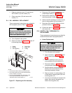
i. Replace protective cover (13) and secure
with washers (15) and screws (14).
j. Close cover door (16) and secure with
screws (17).
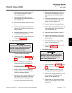
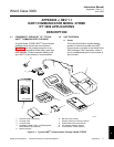
E-11 GUI ASSEMBLY REPLACEMENT
These replacement instructions are provided for
GUI equipped systems. Refer to Figure E-7.
Disconnect and lock out power before
working on any electrical components.
There is voltage up to 240 Vac, and
could cause personal injury.
a. Turn off power to the system.
b. Open cover door (43, Figure E-7) of the IFT
by removing screws (5).
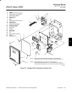
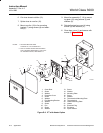
1. Screw
2. Washer
3. GUI Assembly
4. Cover Door
5. Screw, M4
6. O-Ring
E
N
T
E
R
E
S
C
D
A
TA
C
A
L
S
E
T
U
P
H
E
L
P
NOTES:
1.
2.
GUI MOUNT AREAIS PART OF COVER DOOR.
GUI FACES INSIDE OF IFT ENCLOSURE WHEN
COVER DOOR IS CLOSED.
3.
NOT ALL PARTS SHOWN ARE AVAILABLE FOR
PURCHASE SEPARATELY. FOR A LIST OF
AVAILABLE PARTS, SEE TABLE E-3.
(SEE
NOTE 1)
1
2
3
4
5
6
21240001
Figure E-7. Replacing the GUI Assembly
c. Disconnect GUI assembly cables from mi-
croprocessor board (11, Figure E-6).
d. Remove GUI assembly (3, Figure E-7) by
removing screws (1) and washers (2).
e. Attach new GUI assembly to inside of cover
door (4) with washers (2) and screws (1).
f. Reconnect GUI assembly cables to micro-
processor board (11, Figure E-6).
g. Close cover door (4, Figure E-7) and secure
with screws (5).
E-12 HEATER / FAN / THERMOSWITCH
REPLACEMENT
These replacement instructions are provided for
heater/fan/thermoswitch equipped systems.
a. Heater Replacement
Disconnect and lock out power before
working on any electrical components.
There is voltage up to 240 Vac, and
could cause personal injury.
1. Turn off power to the system.
2. Open cover door (1, Figure E-8) of the
IFT by removing screws (5, Figure
E-7).
3. Remove protective cover (4) by re-
moving screws (2) and washers (3).
4. Disconnect cable (1, Figure E-6) from
microprocessor board (11, Figure E-6).
5. Partially remove mounting plate as-
sembly (15) from enclosure (23) by
removing necessary screws.
6. Remove screws (11) and washers (12)
to free heater mounting plate (20) from
mounting plate (15).
7. Cut wires to old heater (21) close to the
heater; then remove old heater from
heater mounting plate (20).