


Instruction Manual
Appendix E Rev. 4.5
June 1999
E-10 Appendices Rosemount Analytical Inc. A Division of Emerson Process Management
World Class 3000
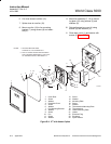
l. Reinstall mounting plate (10) to enclosure
(6) with the necessary screws and washers.
m. If removed, replace thermoswitch assembly
(18, 19, Figure E-8) and secure with screws
(13) and washers (14).
n. Reinstall the wires to the terminal strip on
interconnect board (12) as was noted in
step e.
o. Connect cable (1) to the receptacle on mi-
croprocessor board (11). Reconnect GUI
assembly cable to receptacles on micro-
processor board if IFT is equipped with GUI.
p. Replace protective cover (13) and secure
with washers (15) and screws (14).
q. Close cover door (16) and secure with
screws (17).
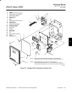
E-8 POWER SUPPLY BOARD REPLACEMENT
Disconnect and lock out power before
working on any electrical components.
There is voltage up to 240 Vac, and
could cause personal injury.
a. Turn off power to the system.
b. Open cover door (16) of the IFT by remov-
ing screws (17).
c. Remove protective cover (13) by removing
screws (14) and washers (15).
d. Disconnect cable (1) from the receptacle on
microprocessor board (11). Disconnect GUI
assembly cable from receptacles on micro-
processor board if IFT is equipped with GUI.
e. Carefully tagging wires, remove the wires
from terminal strip on interconnect board
(12).
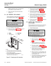
f. If unit is equipped with heater option, re-
move thermoswitch assembly (18, 19,
Figure E-8) by removing screws (13) and
washers (14).
g. Remove mounting plate (10) by removing
the necessary screws.
h. If unit is equipped with heater option, dis-
connect plug from J2 on power supply
board (4, Figure E-6) by squeezing tabs in
and pulling connector up.
i. If unit is equipped with heater option, re-
move fan assembly (7, 10, Figure E-8) by
removing screws (5) and washers (6).
j. Disconnect the transformer cable plugs from
the receptacles on power supply board (4,
Figure E-6).
k. Carefully tagging wires, remove the wires
from terminal strips J5 and J6 on power
supply board (4, Figure E-6).
l. Remove power supply board (4) from en-
closure (6) by removing screws (2) and
washers (3).
m. Attach new power supply board (4) to en-
closure (6) with screws (2) and washers (3).
n. Reconnect the wires as noted in step e.
o. Connect the transformer cable plugs from
transformer (9) to the receptacles on power
supply board (4).
p. If removed, install fan assembly (7, 10,
Figure E-8) and secure with screws (5)
and washers (6).
q. If disconnected, reconnect plug to J2 on
power supply board (4, Figure E-6).
r. If removed, replace thermoswitch assembly
(18, 19, Figure E-8) and secure with screws
(13) and washers (14).
s. Reinstall mounting plate (10) to enclosure
(6) using the necessary screws.
t. Reconnect the wires to interconnect board
(12) as noted in step e.