


Instruction Manual
748374-F
March 2003
Rosemount Analytical Inc. A Division of Emerson Process Management Appendix B. User Interface Help 8-1
Model NGA2000 TO2
SECTION 8
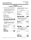
APPENDIX B. USER INTERFACE HELP
This section provides a means of rapidly finding
any desired function or configuration factor in
the menu system.
The NGA menu system is necessarily complex
due to the wide variety of configuration possibili-
ties available with the NGA architecture.
This section consists of a series of titles describ-
ing the function or configuration desired, with a
series of menu titles that show the path taken to
that function.
The menu selections are sometimes abbrevi-
ated; Basic Controls is referred to as Basic for
example, Expert controls and setup as Expert,
and Technical level as well as Technical.
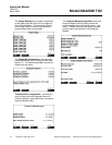
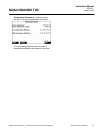
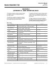
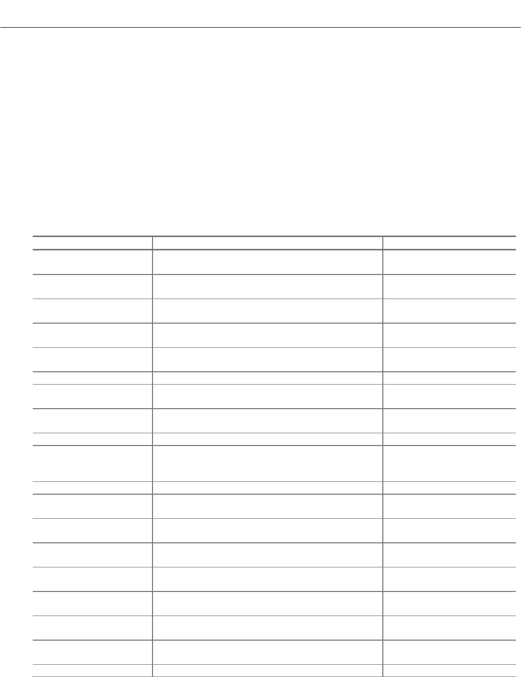
Menu Items
ITEM PATH NOTES
Add a service date
Technical - Service menus - Service history -
Analyzer module history - Add service date!
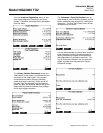
Alarm enabling
Technical – Listing of all modules – Analog I/O –
Select I/O module - Relay status
Analyzer specific
alarms
Expert - Auxiliary module setup - Select Analog
output module – Alarm conditions
v 2.3 only
Analyzer diagnostics
Technical - Diagnostic menus - Analyzer mod-
ule diagnostics
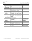
Analyzer specific con-
trols (remote)
Expert - Auxiliary module setup - Select Analog
output module – Input line control
v 2.3 only
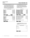
Binding Technical - System setup – Module Binding
Displayed parameters
Expert - Analyzer module setup - Displayed pa-
rameters
Electrolyte level
Technical - Diagnostic menus - Analyzer mod-
ule diagnostics - Physical measurements
Exit sleep mode Basic
Gas scale factor
Technical - Diagnostic menus - Analyzer mod-
ule diagnostics - Calibration parameters - Gas
scale factor
Initiate quick start Basic
Last service date
Technical – Service menus – Service history –
Analyzer module history
User updated
List of detected NGA
modules
Technical - Listing of all modules
Jumps from there into their
diagnostic screens
Load factory calibration
data
Technical - Diagnostic menus - Analyzer mod-
ule diagnostics - Calibration parameters
Required when changing
sensor
Manufacturing data
Technical – Service menus - Manufacturing
data - Analyzer module data
Maximum range
Expert - Analyzer module setup - Range set-
tings
Maximum range upper
limit
Minimum range
Expert - Analyzer module setup - Range set-
tings
Minimum range upper limit
Power supply voltages
Technical – Diagnostic menus – Analyzer mod-
ule diagnostics - Power supply voltages
Quick start status Basic