


Instruction Manual
748374-F
March 2003
Rosemount Analytical Inc. A Division of Emerson Process Management Installation 2-1
Model NGA2000 TO2
SECTION 2
INSTALLATION
2-1 UNPACKING
If the Trace Oxygen (TO2) Analyzer Module is
received as a separate unit, carefully examine
the shipping carton and contents for signs of
damage. Immediately notify the shipping carrier
if the carton or contents is damaged. Retain the
carton and packing material until all components
associated with the TO2 Analyzer Module are
operational.
2-2 ASSEMBLY
Before installation of the TO2 Analyzer Module,
electrolyte must be added to the Sensor. Follow
the procedure described below under Section 2-
2a below.
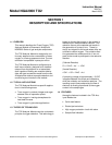
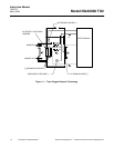
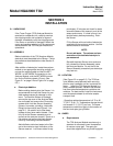
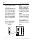
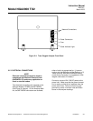
After addition of electrolyte, locate the analyzer
module on an appropriate mounting surface and
connect the network cable to either the NET-
WORK 1 or NETWORK 2 connection on the
Analyzer Module, and the NETWORK connec-
tion on the Platform network I/O port. (See
Figure 2-1 on page 2-2 and Figure 2-4 on page
2-5.)
a. Electrolyte Addition
Before adding electrolyte to the Sensor, it is
recommended to check the Sensor for pos-
sible leakage caused by damage in ship-
ment. To check the Sensor for leakage,
remove the top cover of the Analyzer Mod-
ule and locate and remove the 5 mounting
screws which hold the Sensor Assembly
(Sensor, flow meter, plumbing, inlet/outlet
fittings) to the module (see Figure 4-1 on
page 4-1). Be careful not to lose these
screws as they have metric threads. Care-
fully lift out the Sensor assembly and re-
move from the analyzer module. Place on a
flat surface and remove the black Sensor
cover by unscrewing counterclockwise.
Add distilled or deionized water to the Sen-
sor to the maximum level indication on the
Sensor reservoir. Let Sensor stand for ap-
proximately 15 minutes and check for leaks
around the base of the reservoir, and at the
seams and corners. If a leak is found, con-
tact the factory before proceeding. Drain
the Sensor.
Fill the Sensor with one bottle of electrolyte
supplied with the analyzer module. Use the
entire contents of the bottle.
NOTE:
Do not add water. The volume and con-
centration of the bottled electrolyte is
pre-measured.
Reinstall the black Sensor cover and care-
fully reinstall the Sensor Assembly inside
the Analyzer Module. Do not the tilt the
Sensor Assembly excessively as electrolyte
may leak out.
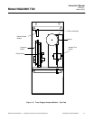
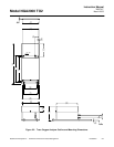
2-3 LOCATION
(See Figure 2-2 on page 2-3) The TO2 Ana-
lyzer Module comes standard with mounting
ears for easy installation on flat, horizontal sur-
faces. , Install the TO2 Analyzer Module in a
clean, weather-proofed, vibration-free location
free from extreme temperature variations and
moisture. For best results, install the instrument
near the sample stream to minimize sample
transport time.
, Operating ambient temperature is 0 °C to 45
°C (32 °F to 81 °F). Temperature change should
not exceed 10 °C (18 °F) per hour. The same
temperature restrictions apply to the location of
the zero and span gas cylinders.
2-4 GASES
a. Requirements
The TO2 Analyzer Module requires only a
standard of accurately known composition
for use as a span gas. The span gas
should be supplied from a cylinder equipped