


Instruction Manual
748374-F
March 2003
Rosemount Analytical Inc. A Division of Emerson Process Management Installation 2-5
Model NGA2000 TO2
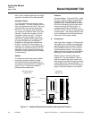
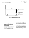
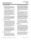
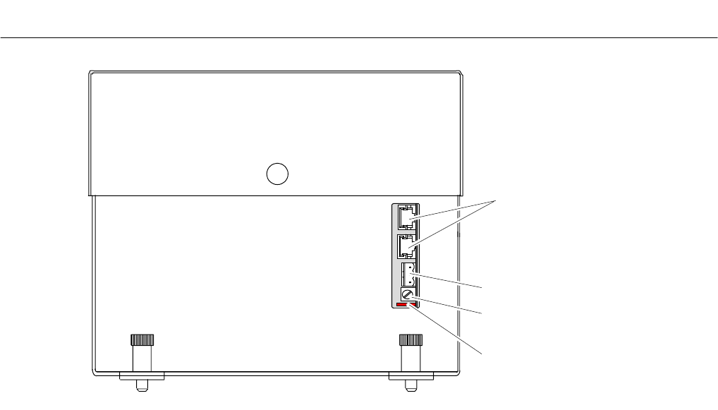
Network Connections
Power Connection
Fuse
Power Indicator Light
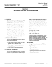
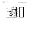
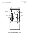
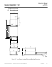
Figure 2-4. Trace Oxygen Analyzer Front Panel
2-5 ELECTRICAL CONNECTIONS
NOTE
Electrical connnections must be made in
compliance with National Electrical Code
(ANSI/NFPA 70) and/or any applicable na-
tional or electical codes.
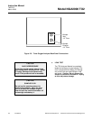
Two electrical connections are required on the
Analyzer Module: POWER and NETWORK
(See Figure 2-4 above). On the Analyzer Mod-
ule, two NETWORK connectors are available,
either of which is appropriate for: 1) intercon-
nection with the Backplane of the Platform or 2)
"daisy-chaining" with other NGA2000 compo-
nents (A star connection is acceptable for LON
lengths under about 10 meters.)
Connect a source of 24 V 5A DC power to the
power inlet. Make sure that the ground connec-
tion is made, and that this is separate from the
power return lead. Failure to ensure a good
ground may result in random noise and distur-
bance in the analyzer readings.