


Instruction Manual
748374-F
March 2003
2-2 Installation Rosemount Analytical Inc. A Division of Emerson Process Management
Model NGA2000 TO2
with a clean, metallic diaphragm, two-stage
regulator. A shutoff valve is recommended.
Calibration Gases
The TO2 module does not require routine
zero calibration. The zero is factory set and
does not experience routine drift. Over long
periods of time, the zero may experience
minor drift. For low ppm range analyzers,
you may wish to check the zero at one year
intervals. Oxygen-free nitrogen is recom-
mended for use as zero gas. This gas is
certified to <0.5 ppm oxygen and can be
improved by passing the zero gas through
an oxygen scrubber such as Millipore™
Waferpure or Semigas Nanochem® resin
purifiers. A mixture of trace oxygen in a
background of nitrogen is recommended as
span gas. For maximum accuracy, the con-
centration of trace oxygen in the span gas
should be as high as possible for the range
of measurement.
Sample
The sample must be clean and dry before
entering the Analyzer Module. Sample
should be filtered for particulates down to
two microns, and should have a dewpoint at
least 5 °C (13 °F) below the coldest ex-
pected ambient temperature.
Pressure
Constant between 13.8 and 69 hPa - gauge
(0.2 and 1.0 psig) sample inlet pressure is
recommended. If a needle valve is used
upstream of the Analyzer Module to control
flow, the inlet pressure to the needle valve
should not exceed 345 hPa (5 psig). A
constant sample flow rate between 1.0 to
3.0 SCFH (0.5 to 1.5 l/min) is recommended
for best results. The Analyzer Module must
vent to atmosphere to avoid back pressure
influences on the oxygen reading.
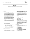
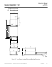
b. Connections
(See Figure 2-3 on page 2-4 ) Connect inlet
and outlet lines for sample to appropriately
labeled fittings on the rear panel. SAMPLE
IN and SAMPLE OUT are 1/4-inch ferrule-
type compression fittings. Zero and span
gases should be introduced at the SAMPLE
IN fitting at normal sample inlet flow rate.
Metallic tubing is recommended for the
sample line. The use of plastic, Teflon, or
other non-metallic tubing can result in am-
bient oxygen permeation through the tubing
causing higher than expected reading. Ex-
haust tubing should be 1/4 inch (6.3 mm) or
larger, and can be metallic or non-metallic.
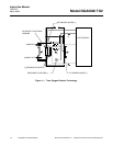
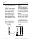
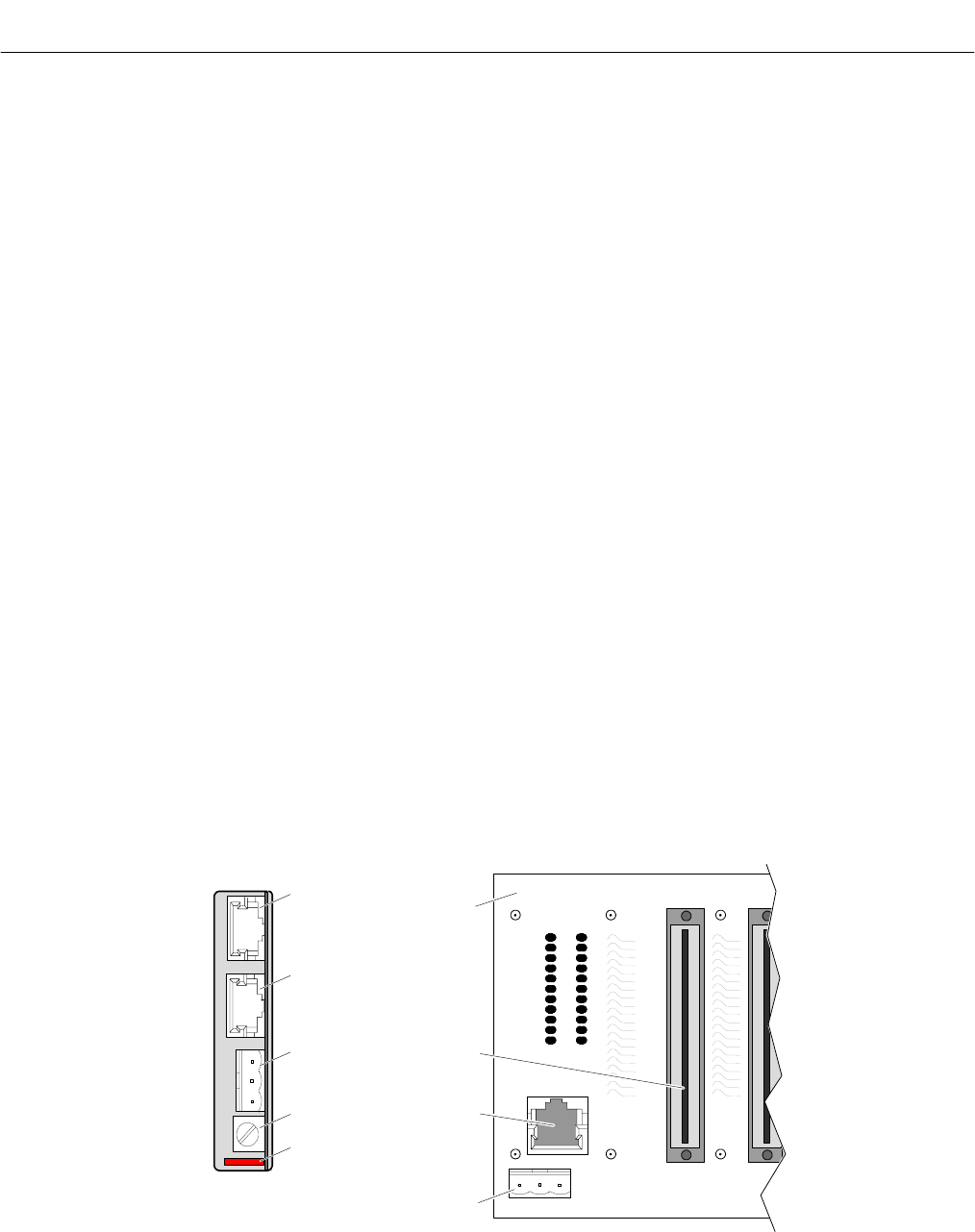
Figure 2-1. Analyzer Module Interconnection with Instrument Platform
ANALYZER MODULE
CONNECTIONS
BACKPLANE
CONNECTIONS
Fuse
Powe
r
Network 2
Network 1
Power Indicator Light
Power
Network
Controller Board
Connector
Backplane