


Instruction Manual
748374-F
March 2003
Rosemount Analytical Inc. A Division of Emerson Process Management Maintenance and Troubleshooting 4-3
Model NGA2000 TO2
Install replacement Sensor in reverse order.
Check Sensor for leaks and add electrolyte as
described in Section 2-2a on page 2-1. Rein-
stall Sensor Assembly in Analyzer Module and
reconnect J5 and J6 to the power board.
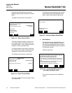
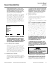
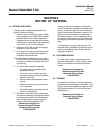
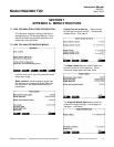
After installation of new Sensor, it will be neces-
sary to load the new calibration data supplied
with the Sensor. Enter the new calibration data
by entering the Load Factory Calibration Data
menu. You can get to this menu as follows:
Main Menu, Technical Level Configuration, Ana-
lyzer Module Diagnostics, Calibration Parame-
ters, Load Factory Calibration Data. This menu
screen will look as follows:
Figure 4-2. Load Factory Calibration Data Menu
The data is supplied with the new sensor and
must be entered exactly as shown on the sen-
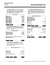
sor data sheet. To enter the data for data points
4 & 5 and the sensor model, press the MORE
soft key to access the next screen.
4-5 FLOW SENSOR REPLACEMENT
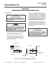
See Figure 1-2 on page 1-3 for Flow Sensor lo-
cation. To replace Flow Sensor, remove all
connecting hardware and undo connections to
the sample line. The Flow Sensor is mounted to
the Sensor Assembly mounting plate by two
screws. Be sure to install the new Flow Sensor
with the flow indication toward the outlet.
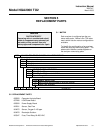
4-6 PRINTED CIRCUIT BOARDS
All three printed circuit boards can be replaced,
if necessary. Refer to Figure 1-2 on page 1-3 for
location of the Power, Network and Computer
Boards.
To remove any PCB, disconnect the associated
cables first. Tag each connector and its location
before disconnecting any wiring. This helps in
reassembly. The Power board and Computer
board are located on a common bracket.
4-7 TROUBLESHOOTING
The following provides a short list of common
troubleshooting tips. Additional information is
contained in the Platform Manual.
The TO2 analyzer fails to purge down to ppm
levels.
Prior to conducting any changes to the system,
try running a quick start sequence (see Section
3-4 on page 3-3) to see if the oxygen reading
goes lower. If the reading does decrease, the
sensor has not been allowed sufficient time to
consume the dissolved oxygen in the electro-
lyte. If the reading continues to read high a leak
may exist in the sample lines. The number one
problem associated with trace oxygen analyzer
installation is the occurrence of leaks in your
sample plumbing. If the oxygen reading will not
come down to ppm levels or is reading higher
than expected, the sample plumbing prior to the
instrument may have a leak. A quick check can
be conducted by observing the oxygen reading
at two different flow levels; 0.5 and 2.0 scfh. If
the oxygen reading drops significantly when the
flow is increased from 0.5 to 2.0 scfh, this is a
good indication that a leak exists.
To check for leaks prior to the sensor, discon-
nect the Analyzer Module and cap the inlet line.
Pressurize the inlet line to 5 - 10 psig and check
all connections with a soapy solution (SNOOP
®
)
to identify leaks.
WARNING
SENSOR DAMAGE
Do not pressure check the sample line with
the sensor connected. Over-pressurization
of the sensor can result in damage.
The TO2 analyzer exhibits flow sensitivity.
Check to make sure that your vent line is not
blocked. If you see a rise in reading with an in-
crease in flow, you may be over-pressurizing
the sensor due to a blocked vent. Since the
Load factory calibration data
Concentration 1:
Output 1:
Temperature 1:
Concentration 2:
Output 2:
Temperature 2:
Concentration 3:
Output 3:
Temperature 3:
HOME ESCAPE MORE